2202MYJE-MY-C8-N_2018.02.
Chapter 4 Operation of Compressor and Unit
Compound 2-stage Screw Compressor 3225**C 4.2 Precautions for Operation
4-7
4.2 Precautions for Operation
If the package unit is used in the refrigeration cycle, please keep in mind the contents of this section in
particular.
4.2.1 Prevention of Liquid Flow-back Operation
Liquid flow-back is a phenomenon where refrigerant that did not completely evaporate with the gas
reaches the compressor. Liquid flow-back may cause insufficient lubrication of the compressor,
abnormal vibrations and noises, and abnormal foaming of lubricating oil (too much oil loss). To prevent
liquid flow-back, properly adjust the expansion valve of each liquid cooler.
For details, refer to Chapter 6 "Troubleshooting" in this manual Chapter 6.
4.2.2 Purging of Non-Condensable Gases
Some types of refrigerants emit bad smells or toxic gases. Make sure to ventilate the
air during work.
When handling fluorocarbon refrigerants, remember that they are prohibited from
being purged into air by law.
If there is a leak on the low-pressure side of the system, air may enter the package unit.
If non-condensable gas like air enters the package unit, the condensing pressure rises and the energy
consumption increases. This leads to uneconomical operation.
Follow the procedure below to check for non-condensable gases.
1. When the compressor is stopped, allow the cooling water to flow to the unit's condenser for at
least 15 minutes. Check the condensing pressure by using the pressure gauge of the compressor.
2. Check the cooling water temperature.
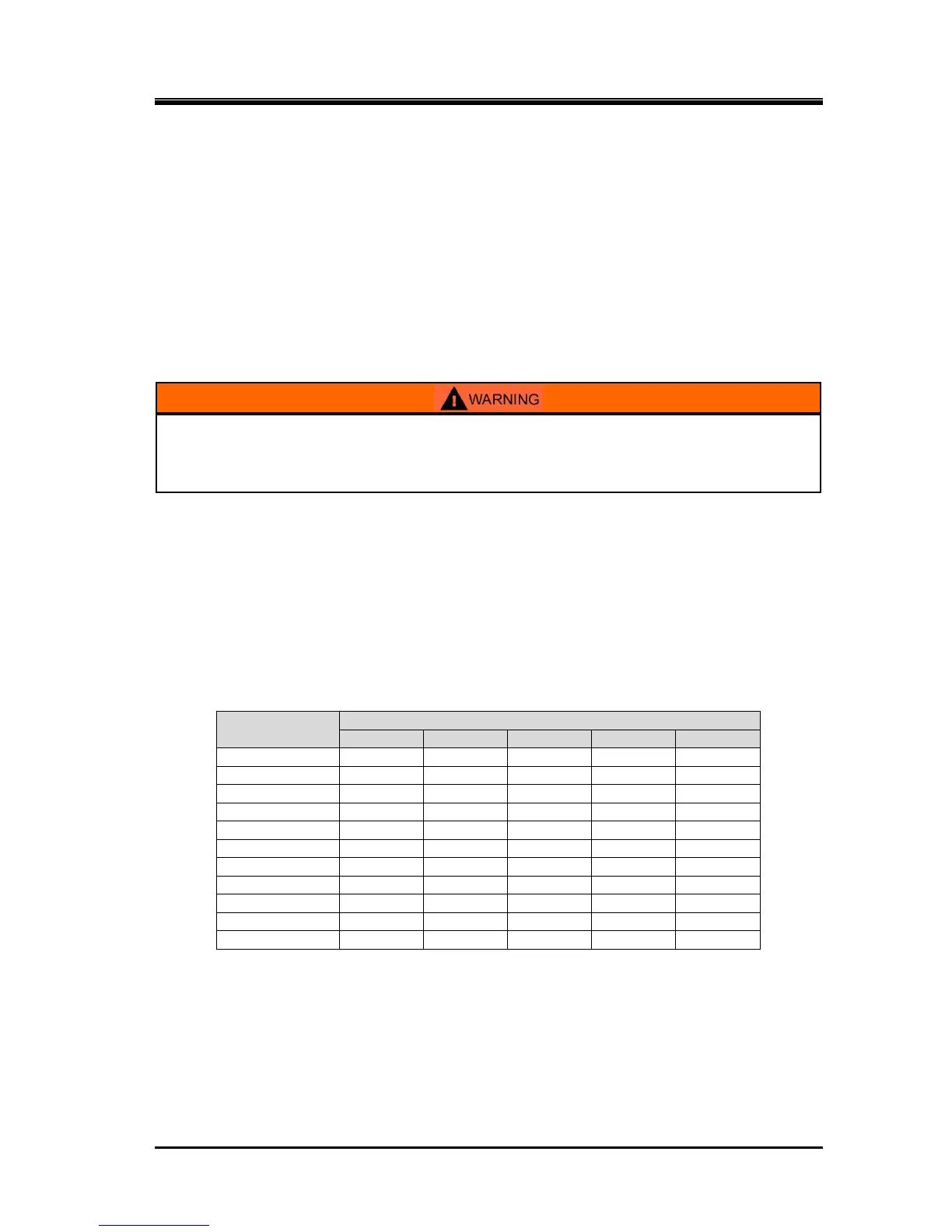
3. Compare the condensing pressure checked in step 1 above with the refrigerant saturation
pressure that depends on the cooling water temperature (as shown in the table below).
Table 4-4 Typical Refrigerant Temperature and Saturation Pressure
■ Unless otherwise noted, the pressure unit MPa represents the gauge pressure in this manual.
4. When the pressure inside the condenser and the refrigerant saturation pressure that depends on
the cooling water temperature are approximately equivalent, non-condensable gases do not exist.
When the pressure inside the condenser is 0.05 MPa or more higher than the refrigerant
saturation pressure that depends on the cooling water temperature, there is a possibility of
non-condensable gases entering the unit. In that case, purge the non-condensable gases from
the condenser.

 Loading...