2202MYJE-MY-C8-N_2018.02.
Chapter 5 Maintenance and Inspection
Compound 2-stage Screw Compressor 3225**C 5.5 Reassembly
5-46
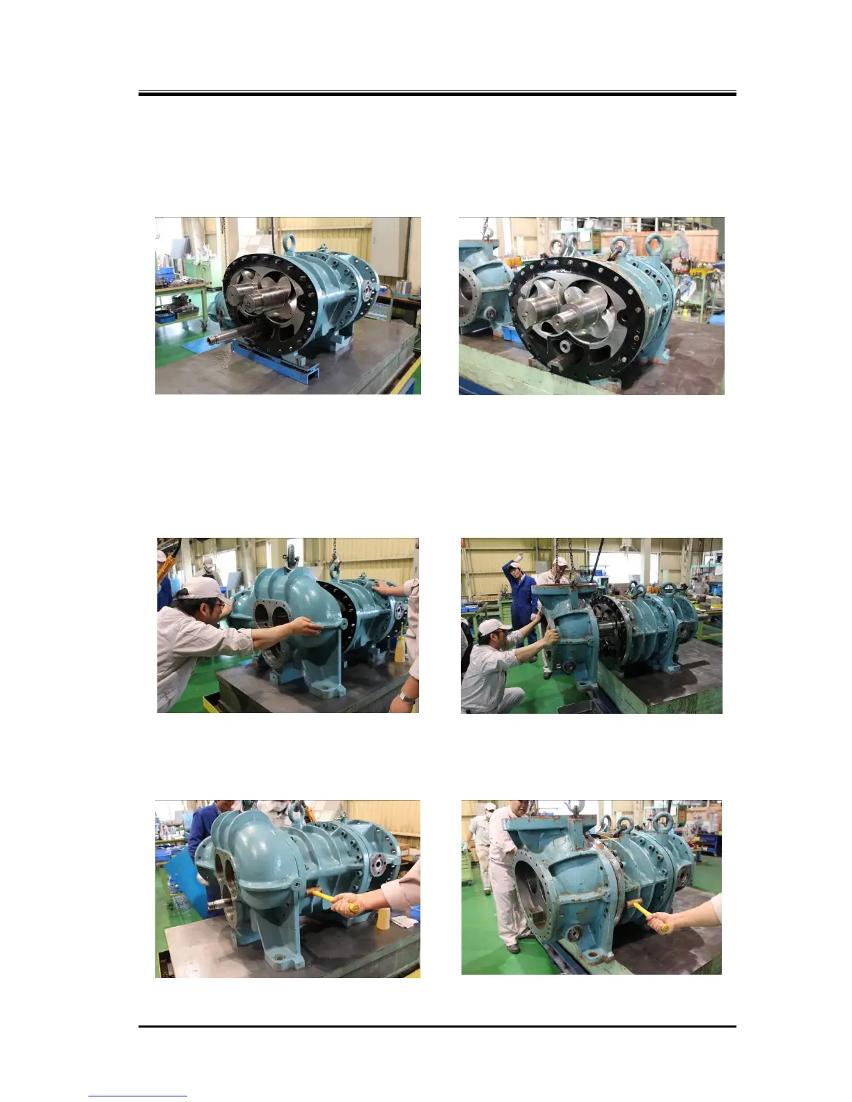
5.5.7 Installing the Suction Cover
a) The gasket of the suction cover [6] is not symmetrically shaped, both for the high-stage and
low-stage.
Apply oil on both sides of the gasket, and attach it to the main rotor casing side while carefully
checking the position of oil supply holes.
b) On the high-stage side, pass the unloader push rod through the hole at the bottom of the suction
cover.
Slide (or use a lifting device to move) the suction cover in parallel along the shaft axis to engage the
rotor shafts with the side bearings. At this time, be careful not to damage the inside surface of the
side bearing by the shaft end.
As the low-stage unloader push rod is out to the bearing head side, be careful only with the rotor
shaft end in this work.
c) After the suction cover has been pushed in up to the flange surface, lightly fasten some of the bolts
[2].
d) Using a copper hammer or an aluminum hammer, drive in the alignment pins [3].

 Loading...