2202MYJE-MY-C8-N_2018.02.
Chapter 5 Maintenance and Inspection
Compound 2-stage Screw Compressor 3225**C 5.4 Disassembly and Inspection
5-26
5.4.7.2 Inspection
Check the hub and sleeve for possible deformation of the gear teeth and wear on each tooth flank.
If it is found abnormal, replace the whole gear coupling assembly. At the same time, investigate the
cause of the abnormality.
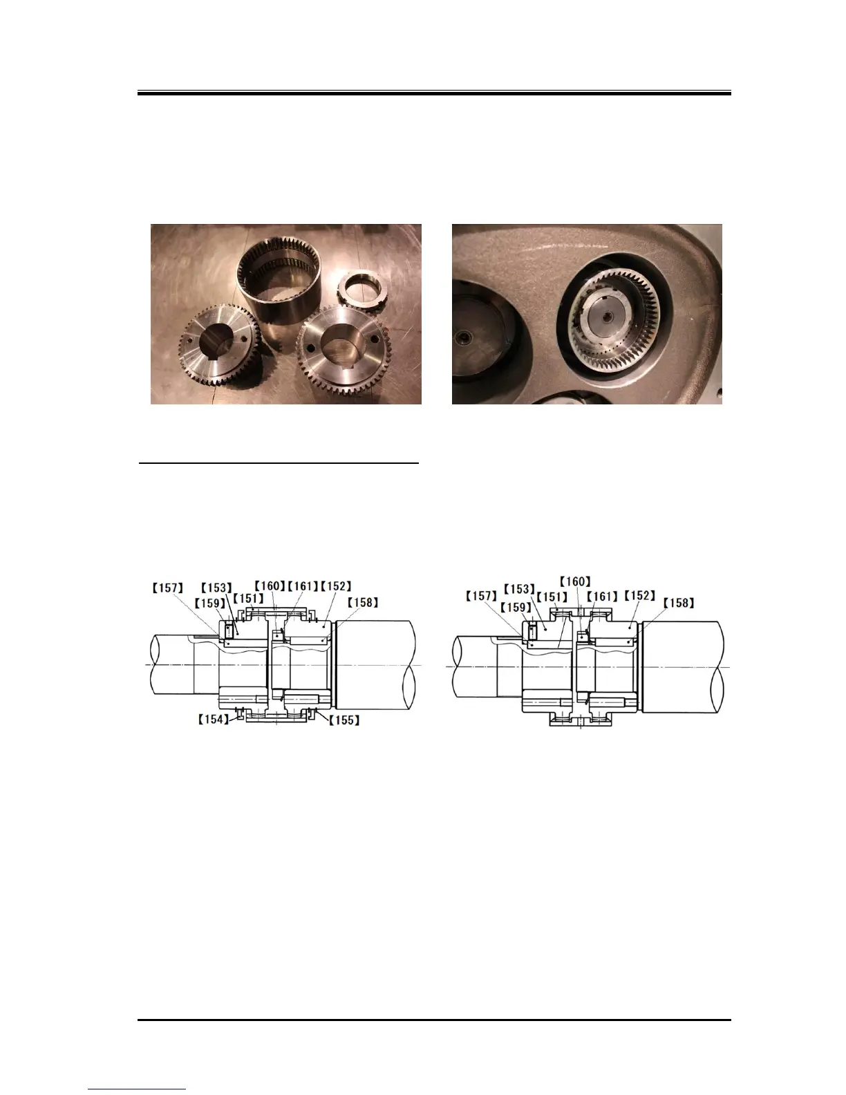
Photo 027: Current Gear coupling parts
Photo 028: Low-stage Gear Coupling
Gear coupling mechanism of 3225**C models
The gear coupling of 3225**C uses a coupling hub and drive sleeve. While the old couplings (before the
design modification made in February 2011) have a stop on both outer ends of the sleeve to prevent the
sleeve from dropping off, the stops are placed on the inside of the drive sleeve after the design
modification (compatible with the old type).
After this design modification, the drive sleeve stopper [154] and stop ring [155] are no more used.
The gear coupling assembly consists of the items
151, 152, 153, 154*2, 155*4, and 159.
The gear coupling assembly consists of the
items151, 152, 153, and 159.
Figure 5-8 Conventional Method (Before the
Design modification in Feb. 2011)
Figure 5-9 New Method (After the Design
modification in Feb. 2011)

 Loading...