2202MYJE-MY-C8-N_2018.02.
Chapter 5 Maintenance and Inspection
Compound 2-stage Screw Compressor 3225**C 5.5 Reassembly
5-56
5.5.10 Bearing Cover
a) Before installing the bearing cover [16], check that
the teeth of the lock washer of the thrust bearing part
have been properly bent to prevent rotation and that
the hexagon head bolts fastening the thrust bearing
gland are with conical spring washers.
b) For ensuring the safety, screw two stud bolts in the
upper bolt holes on the flange of the low-stage
bearing head [11-1].
c) After applying sufficient amount of oil, etc. on the
flange surface of the bearing head as well as on
both sides of the gasket (1) for the bearing cover
[17-1], hang the gasket from the upper stud bolts
and attach the gasket onto the flange surface (Photo
102).
Photo 102
The bearing cover gasket is not symmetric because there is a hole for lubricating
oil line to the mechanical seal block in the left (seal) side.
Be careful that do not mistake the direction of the gasket when attaching onto the
bearing head flange surface. Mistaken the direction of the gasket causes the
lubrication failure to the shaft seal block.
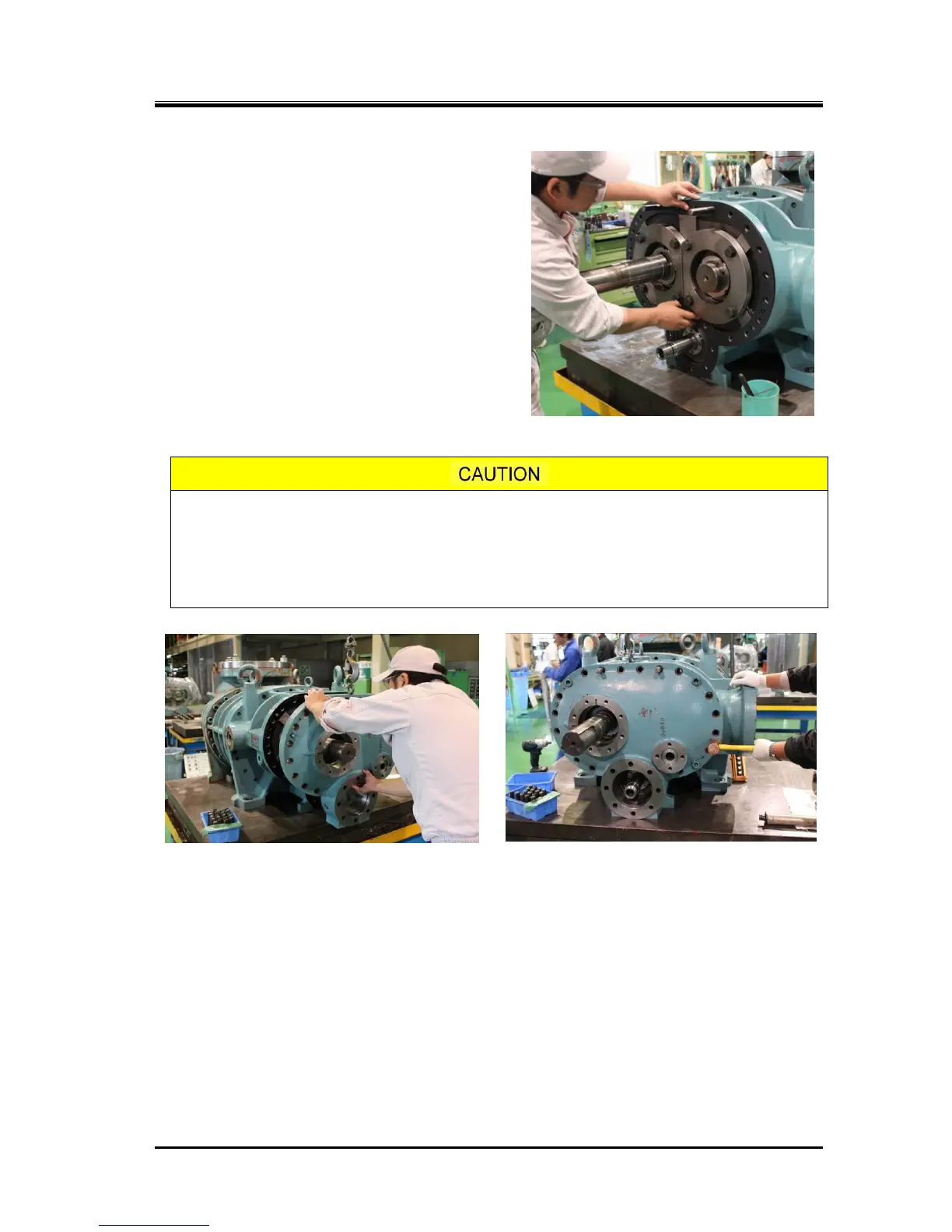
d) While lifting the bearing cover using a lifting hook on the eye bolt, install the bearing cover carefully
not to make contact with the M rotor shaft or the push rod (Photo 103). Once the cover is on the stud
bolts, the lifting hook may be removed.
e) After correctly setting the position of the alignment pins, lightly tap the flange at different places
alternately using a copper hammer or soft hammer to install the cover in position (Photo 104).
f) When the cover has come to the position the bolts can be screwed in, screw in two or three
hexagon socket head cap screws [18-1] and evenly tighten them to reduce the clearance and make
the cover contact the body. Then, tighten all the bolts at the specified torque of 450 N・m.

 Loading...