2202MYJE-MY-C8-N_2018.02.
Chapter 5 Maintenance and Inspection
Compound 2-stage Screw Compressor 3225**C 5.4 Disassembly and Inspection
5-28
5.4.9 Balance Piston
During the operation of a screw compressor, both
the rotation rate and the thrust load of the M rotor
are higher than those of the F rotor. Accordingly,
the service life of the thrust bearing for the M rotor
will be significantly shorter than that of the F rotor,
if no special measures are taken. As such, in
order to reduce the thrust bearing load on the M
rotor side, a hydraulic piston is used on the shaft
end of the rotor drive shaft to cancel the thrust
load.
◆ Note that no balance piston is used on the
low-stage. Because the low-stage pressure
condition is lower than high-stage, the service
life difference of the bearings is not so
significant compared to the high-stage.
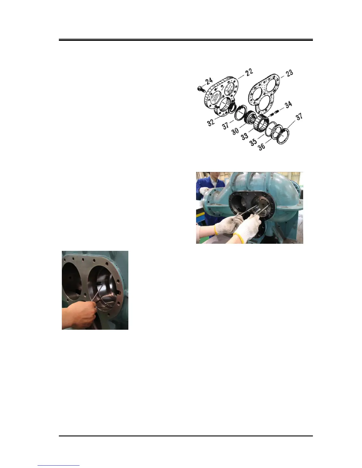
5.4.9.1 Disassembly
a) Remove the snap ring [32] retaining the
balance piston [30] on the shaft using external
snap ring pliers.
b) Pull the balance piston straight out by
screwing two eye bolts into the screw holes.
While the rotor shaft has a balance piston key
[31], it is unnecessary to remove the key.
c) To prevent rotation of the balance piston sleeve [33], there are
hexagon socket head set screws [34] screwed from both the M rotor
side (balance piston) and F rotor side. So, loosen the set screw on
the F rotor side, and place the M rotor side screw under the suction
cover as shown in Photo 032.
d) Remove the snap ring [37] securing the balance piston sleeve using
the internal snap ring pliers. As the snap ring is pressed out by the
internal O-ring [35], slightly pushing it can easily remove the snap
ring.
e) Remove the balance piston sleeve and O-ring.
As clearance fit is used to engage the outside of the sleeve with the
suction cover, you can easily pull it out.
As there is an O-ring spacer [36], also remove the spacer.
5.4.9.2 Inspection
While you will be able to find some trace of wear on the inside surface of the balance piston sleeve,
such wear is not abnormal as it is caused because the clearance between the balance piston and the
sleeve is narrower than the clearance between the rotor shaft and the bearing.
Because enough clearance is given to the outside of balance piston sleeve in order not to apply the
bearing load to the balance piston, no further development of the wear is expected.
However, you should still carefully check the condition because when the side bearing is significantly
worn, the balance piston may also be worn.

 Loading...