2202MYJE-MY-C8-N_2018.02.
Chapter 5 Maintenance and Inspection
Compound 2-stage Screw Compressor 3225**C 5.4 Disassembly and Inspection
5-18
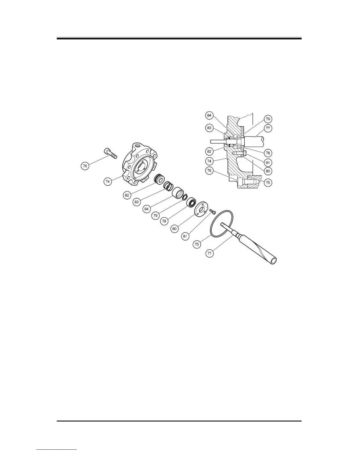
5.4.2 Unloader Cover
The unloader cover [74-1] [74-2] is mounted with the indicator cam [77-1] [77-2], which converts the
linear motion of the unloader slide valve to a rotational motion, and their mounting parts.
The indicator cam is supported by the ball bearing [78] and fixed to the cover with a bearing gland [80].
To make it airtight, the V-ring [82], spring [83], and spring retainer [84] are also attached.
The indicator cam has a spiral groove of 340° to cover the moving range of the unloader slide valve.
The indicator cam shaft is rotated being pushed by the guide pin [68-1] [68-2] on the top end of the
unloader push rod [67-1] [67-2].
Figure 5-4 Unloader Cover Block
5.4.2.1 Disassembly
a) Unscrew and remove the unloader cover mounting hexagon socket head cap screws [76-1] and
[76-2].
b) Pull the cover out in the direction parallel to the axis of the push rod in the unloader cylinder.
Carefully pull it straight, because if the unloader cover is pulled sideways, the shaft of the indicator
cam may be bent.
c) If the indicator cam will not move normally, check the spiral groove of the indicator cam, bearing,
and guide pin. The disassembly sequence is as follows:
c-1) As the bearing gland [80], which fixes the indicator cam in place, is secured by three
hexagon socket head cap screws [81] on the cylinder side of the unloader cover, unscrew
and remove these bolts.
c-2) Then, the indicator cam can be pulled out with the ball bearing [78] and the snap ring
(retaining ring) [79] attached to the shaft.
c-3) Inside the unloader cover, the spring retainer [84], spring [83], and then V-ring [82] are
assembled in this order. Because the V-ring is tightly engaged with the bore of the
unloader cover, the lip of the V-ring will be damaged when it is once removed, making it
unusable again. Therefore, be sure to replace it with a new one once it is disassembled.

 Loading...