2202MYJE-MY-C8-N_2018.02.
Chapter 5 Maintenance and Inspection
Compound 2-stage Screw Compressor 3225**C 5.4 Disassembly and Inspection
5-25
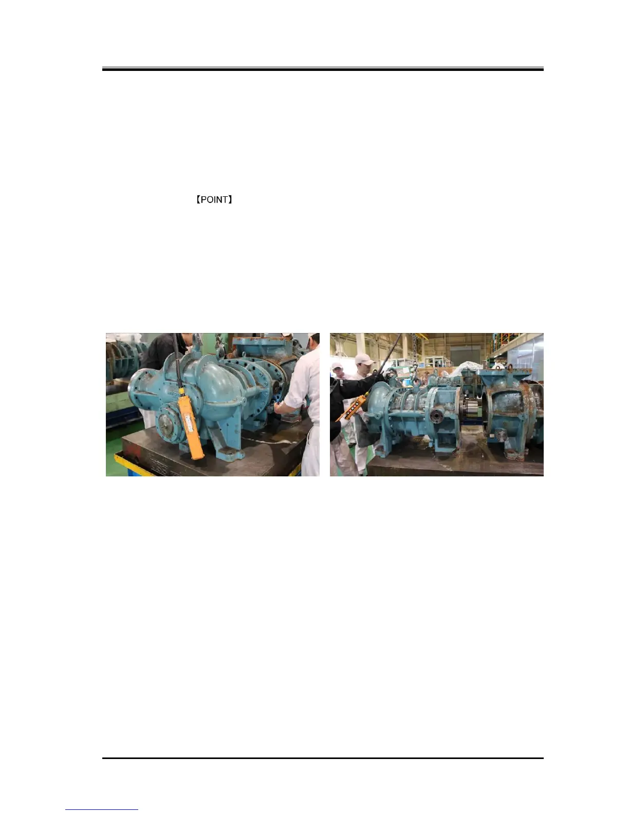
5.4.6 Separating High-stage and Low-stage Blocks
The high-stage and low-stage blocks should be separated before inspecting the gear coupling,
high-stage thrust bearing, main bearing, pulled out rotors, etc.
As explained at the beginning of Section 5.4 of this chapter, the separation may be done at the initial
step of the overhaul work.
5.4.6.1 Disassembly
a) As it is explained in the Section 5.3.5, the bolts on the bottom side must be removed by
placing the compressor on a special stand before starting the disassembly work.
b) Remove the hexagon socket head cap screws [18-2] that fasten the high-stage bearing head [11-2]
to the low-stage suction cover [5-1].
c) As the gasket [17-2] is sticking to both surfaces of the high-stage bearing head and the low-stage
suction cover, use the bolts [18-2] that have been removed to screw them into the jacking threads in
the bearing head to evenly push the suction cover to separate the two blocks.
d) The gear coupling assembly [151 to 161] for power transmission is located inside, on the side of the
M rotor shaft.
As the drive side and driven side of the coupling can be separated along the shaft axis, move the
main body exactly along the shaft axis to separate them.
5.4.7 Gear Coupling
The gear coupling, which is used as a power transmission means, is divided into the high-stage and the
low-stage blocks, with each block attached to the corresponding M rotor shaft, and these two blocks are
directly connected by a drive sleeve.
5.4.7.1 Disassembly
a) The drive sleeve [151] can be removed by hand after the high-stage and low-stage are separated.
b) On the high-stage (driven) side, first loosen the knurled cup point socket set screw [159] on the
driven hub used for locking, and then pull out the driven hub. The driven hub can be easily pulled
out, as clearance fit is used.
c) To remove the low-stage drive hub [152], release the locking teeth of the lock washer [161] and
loosen the lock nut [160].
d) There are two screw holes in the drive hub.
Screw M8 eye bolts into these screw holes and pull out the drive hub. It can be easily pulled out, as
clearance fit is used.

 Loading...