2202MYJE-MY-C8-N_2018.02.
Chapter 5 Maintenance and Inspection
Compound 2-stage Screw Compressor 3225**C 5.4 Disassembly and Inspection
5-15
5.4.1 Unloader Indicator
Because the type 3225**C has a capacity control mechanism also on the high-stage, there are two
unloader indicator locations. The standard operation method is such that the capacity control is used
only on the low-stage during operation, and the capacity control on the high-stage is used to reduce the
load during the startup phase.
As a different control method may be used depending on the system, refer to the separate electrical
control schematic diagram for the plant.
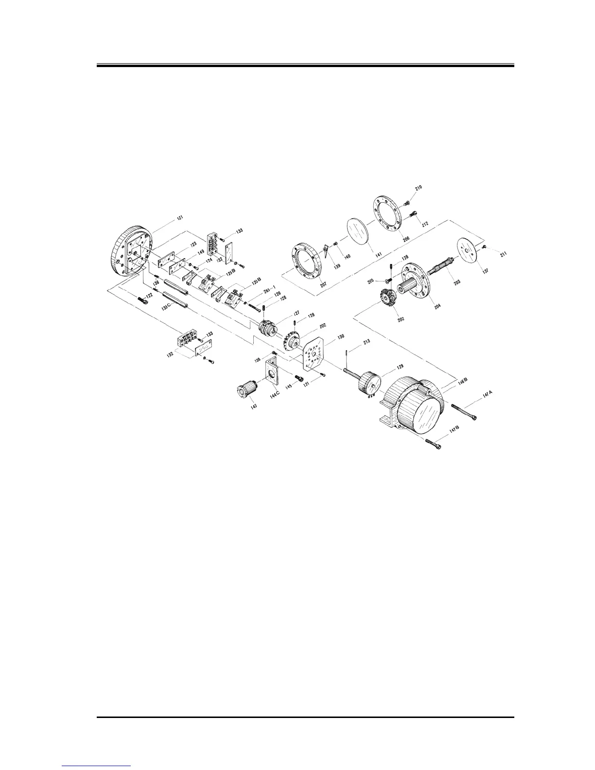
Figure 5-2 Exploded View of the Standard Low-stage Indicator for 3225**C
5.4.1.1 Disassembly
■ In Case of Removing the Wiring only
When removing the wiring of the unloader indicator upon removing the compressor, it is necessary
to remove the cover as the indicator has a terminal block for the wiring. Perform the work according
to the following procedure, and after removing the wires, attach the cover to them for protection.
○ Low-stage
a) Loosen the hexagon socket head cap screws [212] that are fastening the indicator glass [141]. In
this, do not loosen the Phillips screws [210] on the same surface. In this way, the assembly
consisting of the parts [141], [202 to 207], [210], and [211] can be removed.
b) By removing the two each hexagon socket head cap screws [147A] and [147B] that are used to
fasten the indicator cover [146B], the cover can be removed.
c) As you can see the terminal block, remove the plastic cover on the block, and then remove the
screws to disconnect the wires.

 Loading...