2202MYJE-MY-C8-N_2018.02.
Chapter 5 Maintenance and Inspection
Compound 2-stage Screw Compressor 3225**C 5.3 Compressor Disassembly Preparation
5-13
5.3.5 Removing and Lifting the Compressor
The work to lift up or move the compressor must be performed by a qualified operator.
Make sure that the lifting equipment and wires have sufficient load capacity for the
compressor.
Never try to perform disassembly or assembly while the compressor is lifted in the air.
As the suction pipe is located immediately above the compressor, lift up or partially remove the pipe
such that it will not interfere with the lifting device.
For the lifting positions of the compressor, refer to Photo 002 or Figure 3-1 in page 3-3 of Chapter 3 in
this manual.
If the planned overhaul work includes separation between low-stage and high-stage blocks of the
compressor, place the compressor on a special stand as shown in Photo 003 and then remove eight or
more hexagon head cap screws around the bottom flange part. Never try to remove these bolts while
the compressor is lifted in the air. Note that these bolts cannot be removed once the compressor is
placed on the work bench.
Photo 003: Loosening Lower Flange Fastening Bolts
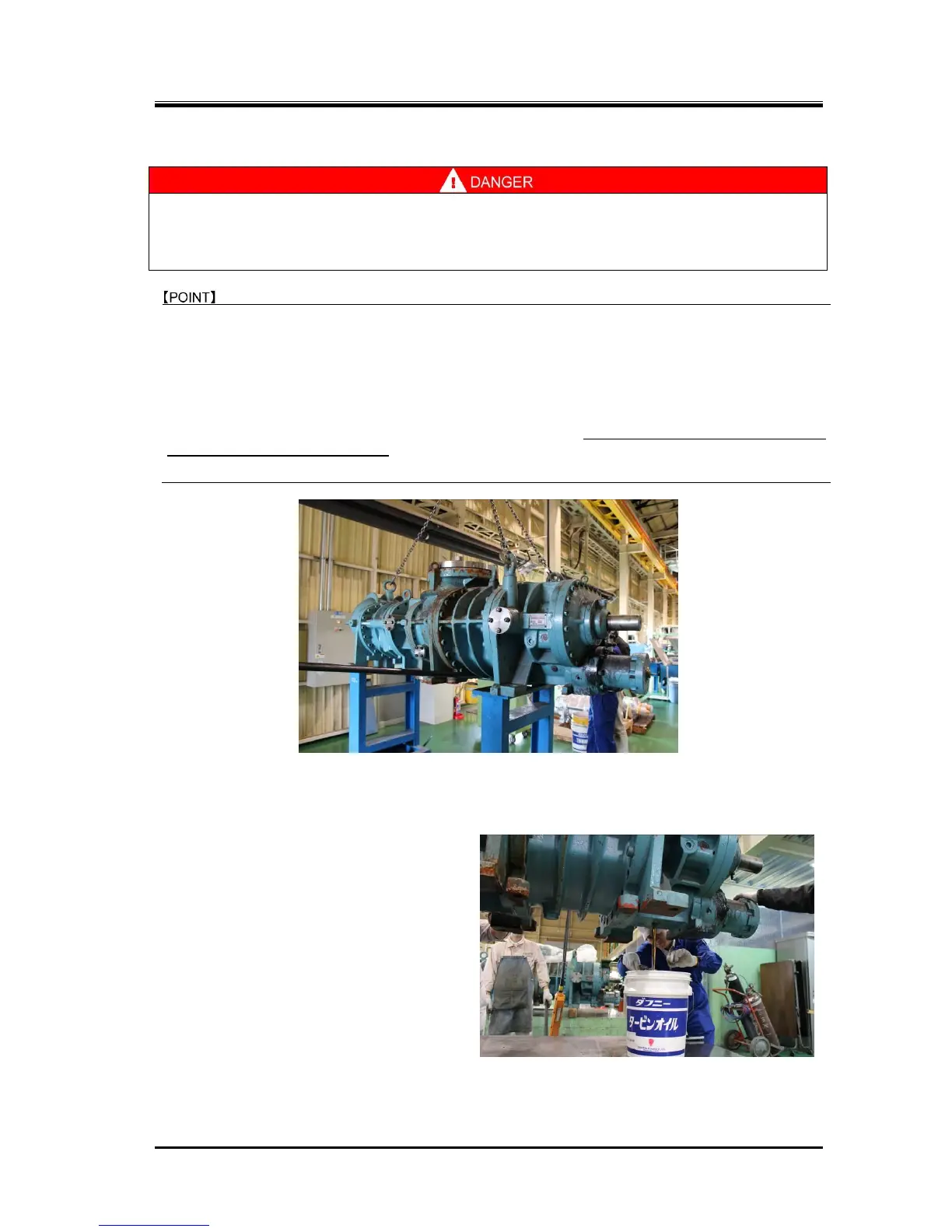
5.3.6 Draining Oil from the Compressor
Because considerable amount of oil is in the
compressor, it is necessary to drain the oil
beforehand.
The drain plugs are located on the bottom of
the suction covers [5-1], [5-2] and on the
bottom of the bearing head [11-1].
The most part of the oil will be drained from
these plug holes.
The remaining oil will be drained as
appropriate in the disassembly process on the
surface plate work bench.
The residual oil will mainly remain inside the a)
unloader cylinder, b) balance piston cover [22],
c) seal cover [51], and suction covers [5-1] and [5-2].
Have oil pans and waste ready to receive oil to be drained during the disassembly process.
Photo 004: Draining Oil from the Bearing Head

 Loading...