2202MYJE-MY-C8-N_2018.02.
Chapter 5 Maintenance and Inspection
Compound 2-stage Screw Compressor 3225**C 5.5 Reassembly
5-49
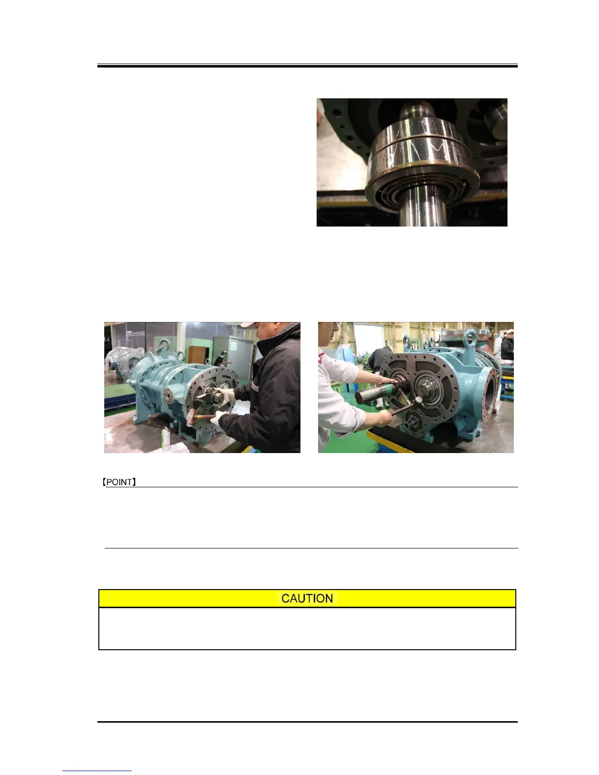
b) If thrust bearing has a "V" marking on the
outer circumference, it means that the
installation direction of the bearing will
sensitively affect the end clearance
adjustment. In this case, the bearing must be
installed with the pointed end of the marking
pointed toward the inside of the machine.
If there is no "V" marking, it means that the
direction of the bearing installation will not
affect the end clearance adjustment. However,
in order to clearly determine the orientation
(whether it is on the inside or outside of the
machine), first combine both bearings with
the bearing number carving facing the outside
of the machine. Then, use a blue whetstone to write the above "V" marking on the bearing to show
the inside direction of the machine. Then, install the bearing (Photo 078).
c) After the thrust bearing has been installed, attach the thrust washer, lock washer, and torsional slip
washer. Then, tighten the lock nut at the specified torque or within the specified range of the
tightening angle (refer to Chapter 7, Section 7.3 "Tightening Torques for Bolts and Nuts" in this
manual) to secure the inner race of the thrust bearing on the rotor shaft.
Tightening the lock nut while keeping the setting position between the lock nut wrench hooks
and the lock nut grooves may cause to make the rotor run-out to enlarge due to uneven
tightening forces.
Change the setting position between the lock nut wrench hooks and lock nut grooves about four
times when fastening the lock nut.
d) Turn the M rotor shaft by hand, to make sure that rotation of rotors is smooth.
As clearance fit is used for the inner race of the thrust bearing, this tightening work is
very important because the bearing is secured only by the tightening force of the
lock nut.

 Loading...