13NIBE F1330
Installation / Adjustment
Pipe connections
Filling and venting the collector system
The brine circuit must be supplied with a pressure expan-
sion vessel. If there is a level vessel this should be replaced.
The brine side should be pressurised to at least 0.5 bar.
The pressure expansion vessel should be dimensioned as
set out in the diagram, to prevent operating disturbances.
The pressure expansion vessel covers the temperature
range from -10 °C to +20 °C at a pre-pressure of 0.5 bar
and the safety valve’s opening pressure 3 bar.
To fill the collector system, mix antifreeze with water in an
open container which connect with filling pump and hoses
as illustrated. The brine should be protected from freezing
down till -15 °C.
Q The valve on the main pipe between service connec-
tions is closed.
Q To fill, start the pump in the filling vessel and allow it to
run until the fluid comes back in the return hose.
Q The fluid can circulate via the mixing vessel until fluid,
without air, returns to the return hose.
Q Stop the filling pump and clean the particle filter. Start
the filling pump again.
Q Open the valve on the main pipe between the service
branches while the filling pump is still operational (to
release the air between the branches).
Q Close the valve on the return hose.
Q Pressurise the system (to max 3 bar) with the filling
pump.
Q Close the filling valve and stop the filling pump.
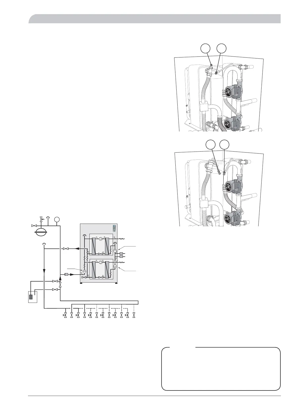
Internal venting valves
Filling the heating medium system
The heating medium system is filled with water until the
required pressure is reached and then vented.
Readjusting, heating medium side (75)
Air is initially released from the hot water and venting
may be necessary. If bubbling sounds can be heard from
the heat pump, the entire system requires further vent-
ing. When the system has stabilised (correct pressure and
all the air removed) the heating controls can be set at the
required value.
Readjusting, brine side (77)
Check that all air is removed from the collector system
by opening the venting valves. The pressure in the brine
circuit is checked with the help of pressure gauges. Filling
of collector system is done by pumping ready mixed brine
through the filling valve.
Venting and filling are repeated until all the air has been
removed and the correct pressure (0.5 - 3 bar) has been
obtained.
AV Shutoff valve
BK Rock collector
EXP Level vessel
JK Soil collector
KB-in Brine in
KB-ut Brine out
KBP Brine pump
SF Particle filter
B
A
A B I II
50.0 C
Varmvattentemperatur
13.43
1.0
A B
BK / JK
KBP
VBP-B
VVR
VVF
VBFB
VBRA/VBRB
KBut
KB-in
VBFA
AV
VBP-A
SF
EXP
P
*
* The brine pump for 60 kW is supplied and installed externally out-
side the heat pump..
F1330 22-40 kW
75
77
F1330 60 kW
77
75
To access and change the speed of the
brine pump (22-40 kW) the circulation
pump’s distribution box must be opened.
The speed is set to ”3” (maximum speed)
upon delivery.
NOTE!
 Loading...


