30 NIBE F1330
Installation / Adjustment
0
0
20
°C
30
5
10
20
Utetemp.
40
15
k=1
k=2
k=3
Description of functions - Basic functions
HPAC
HPAC can either be connected to the Base card or to the
Expansion card 11. When HPAC is to be connected to the
Base card the immersion heater can be run at a maximum
on one step.
Control of cooling mode takes place by means of an
outdoor sensor and, when connected, a room sensor (RG
10/RG 05, see the section Description of functions - Basic
functions > Room control for a description of the connec-
tion).
The control of cooling to the house takes place according
to the set curve slope and curve offset in menus 6.4.2 and
6.4.3. After adjustment, the house receives the correct
amount of cooling for the prevailing outdoor temperature.
The flow temperature from HPAC will fluctuate around the
theoretical required value (value in brackets in menu 2.0).
In the event of excess temperature, F1330 calculates a
surplus in the form of degrees-minutes, which means that
the connection of cooling production is accelerated the
greater the excess temperature that temporarily prevails.
F1330 automatically switches to cooling mode when the
outdoor temperature exceeds the set value in menu 6.4.5.
Passive cooling means that F1330, with the help of the cir-
culation pumps, circulates fluid from the soil/rock collector
in the house’s distribution system and cools the house.
In the event of a large cooling requirement where passive
cooling is not sufficient, active cooling is engaged at the
limit value set in menu 6.4.7. A compressor then starts and
the cooling produced circulates to the house’s distribution
system and heat is circulated out to the soil/rock collector.
When more compressors are available, these will start with
a difference on the set degree-minute setting in menu
6.4.8.
The outline diagram with docking instructions is
available at www.nibe.eu
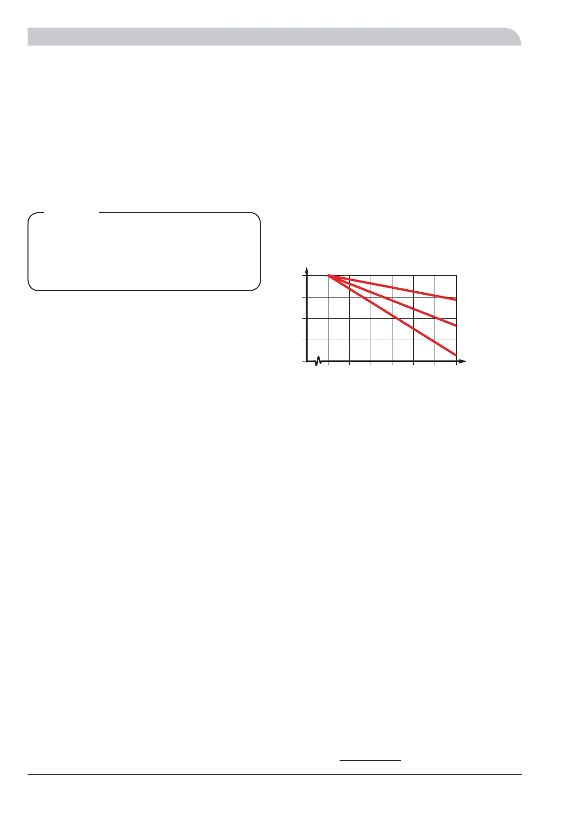
Three different cooling curves can be selected,
see the figure for a detailed description.
If room sensors (RG 10/RG 05) are connected, cooling
starts at a 1 degree excess temperature in the room and
the supply calculation counts on an outdoor temperature
of 30 °C (if the outdoor temperature is greater, then the
actual outdoor temperature is used). When the room tem-
perature has fallen to 0.5 degrees of excess temperature,
the cooling is switched off. To prevent self-oscillation in the
heating system, there is a neutral zone between heating
and cooling operations.
Lower shunt (SV-V2) is regulated during cooling operation
in opposite direction to heating operation, which normally
means the shunt closes completely during cooling opera-
This system solution means that the brine
will also circulate through the heating
system. Check that all component parts are
designed for the brine in question.
NOTE!
tion.
Calculated
flow temperature
Outdoor
temperature
c=1
c=2
c=3
 Loading...


