16 NIBE F1330
Installation / Adjustment
Electrical connection
Connection
Q A heat pump must not be connected without the per-
mission of the electricity supplier and must be connect-
ed under the supervision of a qualified electrician.
Q If an miniature circuit-breaker is used this should have
a motor characteristic D (compressor operation). For
MCB size see Technical Specifications.
Q When the building is equipped with an earth-fault
breaker, the heat pump should be equipped with a
separate one
Q The F1330 does not include an isolator switch on the
incoming electrical supply. The installation must be pre-
ceded by a circuit-breaker with at least a 3 mm break-
ing gap.
Q If an insulation test is to be carried out in the building,
disconnect the heat pump.
Phase sequence monitor
The phase sequence monitor starts as soon as the power
supply is connected to the heat pump. Check the phase
sequence as shown below.
Q Red LED is lit at correct phase sequence and starts to
flash in event of incorrect phase sequence.
Q If there is a fault in the phase sequence, the heat pump
triggers a brine alarm in both modules.
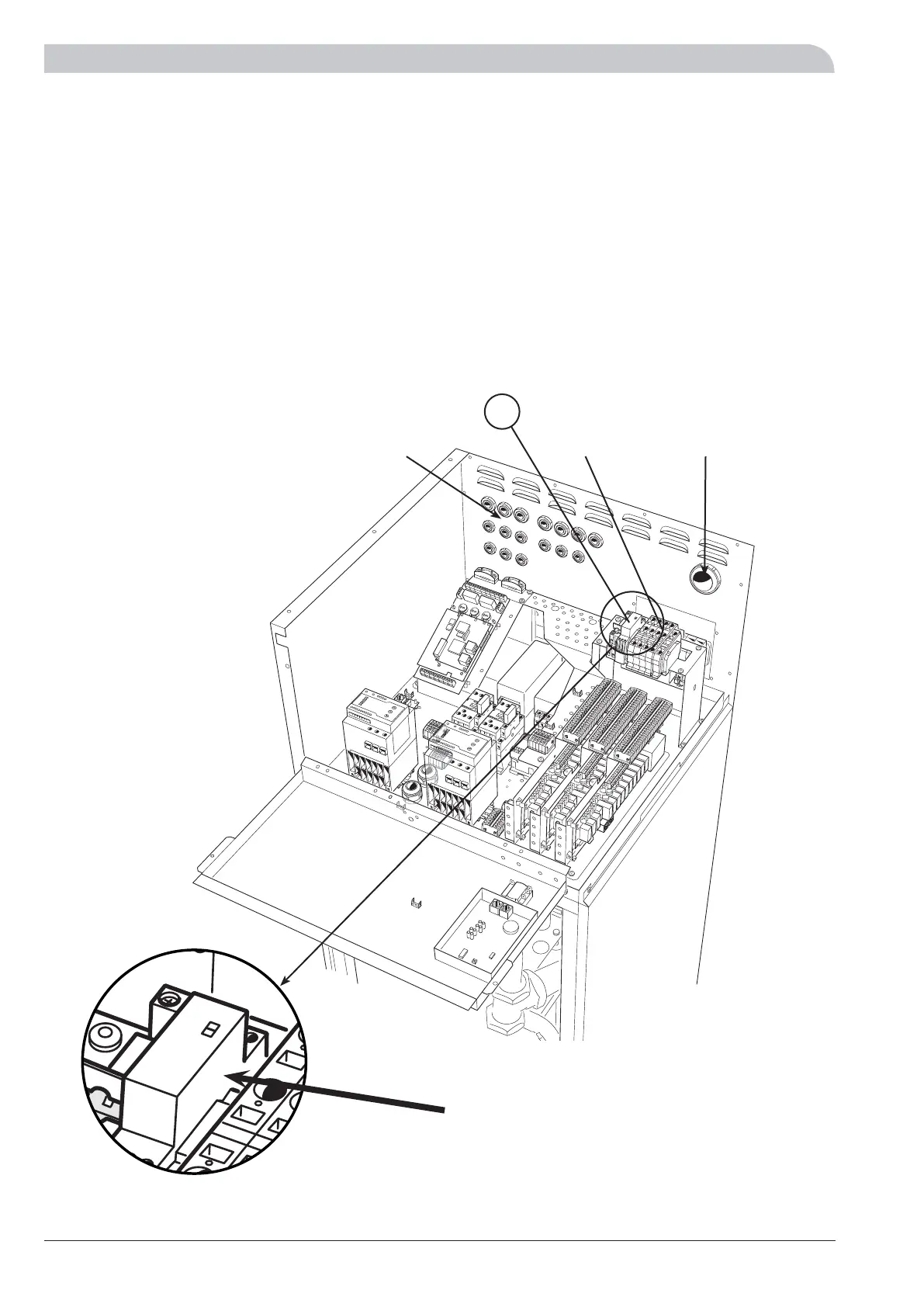
Q Connect the heat pump to the terminal block X9, 400
V 3-phase, neutral + earth via a distribution board with
fuses. Where there is more than one heat pump, each
unit must have a separate supply.
Q Continue the installation by carrying out the inspec-
tion set out in Description of functions - Start up >
Inspection.
Q NOTE! It is not permitted to fit additional compo-
nents in the electrical connection area.
Q Note that F1330 provides 230V control signals that
are intended to control external contactors and
not to drive pumps.
X9, incoming electricity
Supply cable
Sensor cables
LEK
164
The heat pump in the picture is fitted with accessories.
 Loading...


