46 NIBE F1330
Installation / Adjustment
Description of functions – Expansion card 12
Passive and active cooling with 4 pipe system,
PCAC
The cooling system are supplied cooling from the collec-
tor circuit using the circulation pump (CP-K) via the shunt
valve (SV-K).
Passive cooling occurs without the compressor running,
while active cooling occurs when the compressor is run-
ning.
For the installation to work the heating medium must flow
freely, for example using UKV.
Operating mode cooling is activated by the temperature of
the outdoor sensor and any room temperature sensors.
When cooling is required the cooling three-way valve
(VXV-K) and the circulation pump (CP-K) are activated. The
mixing valve regulates to the cooling sensor (KG) and a
cooling set point value that is determined by the selected
cooling curve and offset. Degree minutes (GM) are calcu-
lated in response to the value on the KB out external sen-
sor (KB out ext) and the cooling set point value. GM value
determines in which cooling operation mode the installa-
tion is according to the menu settings.
Control mode: The master KB pump runs according to
the setting in menu 6.7.22.
GM is calculated every 15th min.
Cooling dump mixing valve controls in
response to the cooling dump sensor
and the cooling set point value.
Passive cooling: The master KB pump runs continuously.
Cooling dump mixing valve controls in
response to the cooling dump sensor
and the cooling set point value.
Active cooling: Cooling dump mixing valve closed.
Heating dump mixing valve controls in
response to the heating dump sensor
and the heating set point value.
Electrical connection and menu settings
The shunt valve cooling (SV-K) is connected to terminal
block X6B:9 (230 V reduce signal), X6B:8 (N) and X6B:10
(230 V increase signal).
The shunt valve heat dump (SV-VD) is connected to termi-
nal block X6B:5 (230 V reduce signal), X6B:6 (N) and X6B:7
(230 V increase signal).
The shunt valve cooling dump (SV-KD) is connected to ter-
minal block X6B:13 (230 V reduce signal), X6B:12 (N) and
X6B:16 (230 V increase signal).
Three way valve cooling (VXV-K) and circulation pump
cooling (CP-K) use the potential free relay 13. The relay
can be supplied with voltage internally or externally. With
external connection the voltage and the current must not
exceed 250 V and 6 A. For internal connection the voltage
is 230 V and the current to the function may not exceed
0.4A. Connect the supply from terminal block X13,2:2 to
terminal block X6B:22. The control signal to the three-way
valve and circulation pump is connected to terminal block
X6B:23. The neutral from the functions is connected to
terminal block X13,3:2.
The heat dump signal (VD) is used as a control signal when
we want to dump heat for example with a circulation
pump. The signal is connected to the potential free relay
11. The relay can be supplied with voltage internally or ex-
ternally. With external connection the voltage and the cur-
rent must not exceed 250 V and 6 A. For internal connec-
tion the voltage is 230 V and the current to the function
may not exceed 0.4A. Connect the supply from terminal
block X13,2:2 to terminal block X6B:18. The control signal
to the heat dump is connected to terminal block X6B:19.
The neutral from the dump function is connected to termi-
nal block X13,3:2.
Sensor connections
All sensors are connected to the measurement card.
Heat dump sensor J4:19-20
Cooling dump sensor J4:21-22
Brine out external J4:23-24
Block passive cooling J5:3-4
Block active cooling J5:5-6
Cooling flow line J5:7-8
The outline diagram with docking instructions is
available at www.nibe.eu
LEK
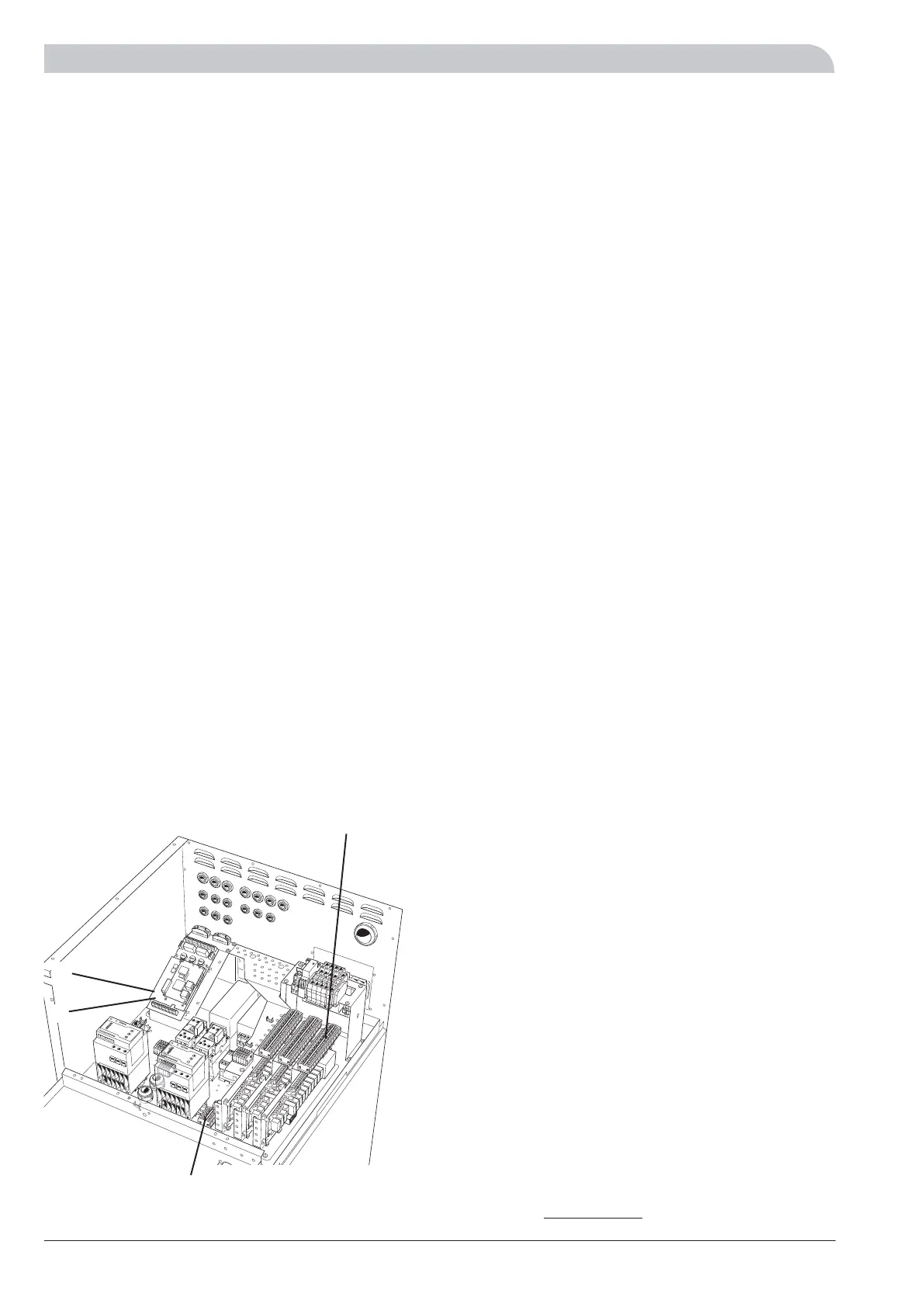
X13
X6b
J5
J4
The heat pump in the picture is fitted with accessories.
 Loading...


