42 NIBE F1330
Installation / Adjustment
Description of functions – Expansion card 12
Passive cooling with 4 pipe system
The cooling system is connected to the heat pump collec-
tor circuit, through which cooling is supplied from the col-
lector via the circulation pump (CP-K) and the shunt valve
(SV-K).
When cooling is required (activated from the outdoor
sensor and any room sensor) the three way valve and the
circulation pump are activated. The shunt valve regulates
so that the cooling sensor (KG) reaches the current set
point value that is equal to the outdoor temperature and
the set min. value for the cooling temperature (to prevent
condensation).
For connection of, and function for, room sensors, see sec-
tion “Description of functions – Basic functions” > “Room
control”.
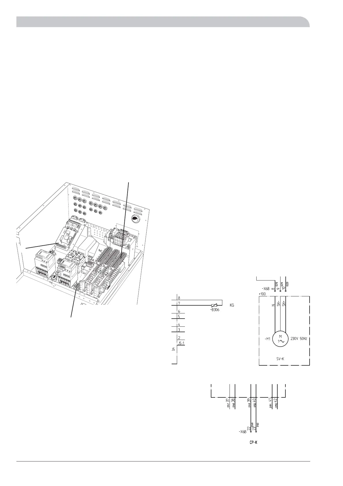
Connection of passive cooling with 4 pipe system
The shunt valve (SV-K) is connected to terminal block
X6B:9 (230 V reduce signal), X6B:8 (N) and X6B:10 (230 V
increase signal).
There is a potential free relay for the circulation pump func-
tion (CP-K), which can be used as control voltage or power
supply (Max 6 A, 250 V). If the relay is used as control
voltage the supply can be bridged internally from X13:2
to X6B:22, use X13:3 as N and then receive the signal on
X6B:23. Max current must be 0.4 A and the control voltage
is 230 V.
External supply to the control signal/power supply for the
circulation pump (CP-K) is connected to terminal block
X6B:22 (max fusing 6 A and 250 V) and the control signal/
power supply is on X6B:23.
For the cooling sensor (KG) location see docking instruc-
tions. The sensors must have a good contact with the
measuring point for best function. If a submerged tube is
not available, use the copper tube supplied.
The sensor is connected to screw terminals J5:7 and J5:8
on the “measurement card”.
LEK
X13
X6b
J5
The heat pump in the picture is fitted with accessories.
+Measure card
+Exp. card 12
 Loading...


