20 NIBE F1330
Installation / Adjustment
LEK
Description of functions - Start up
Master / Slave
F1330 is always delivered as the Master. Up to 8 Slaves
can be connected to the Master. Only one heat pump with
each address can be installed in the same system, i. e. only
one Master and only one Slave 5.
External temperature sensors and control signals should
only be connected to the Master, with the exception of
the shuttle valve/s (VXV) which can be connected one on
each heat pump. See the section Description of functions
- Start up > Operating type selection for setting, as well
as Description of functions - Basic functions > Hot water
production for connecting a shuttle valve (VXV).
Should contact between the heat pumps fail, the Master
will attempt to re-establish communications every ten
minutes. During the period of the communication error,
the text Com. error will be shown as the status of the heat
pump in menu 0.1.x, 5.2.0 and 5.3.0.
When starting a system with several heat pumps, the
Master should never be switched on before the Slaves. If
this does occur, the Master will not the find the Slaves dur-
ing start up and the Slaves will then not work for up to 10
minutes.
In order to reset the heat pump between Master and Slave
1 – 8, proceed as follows:
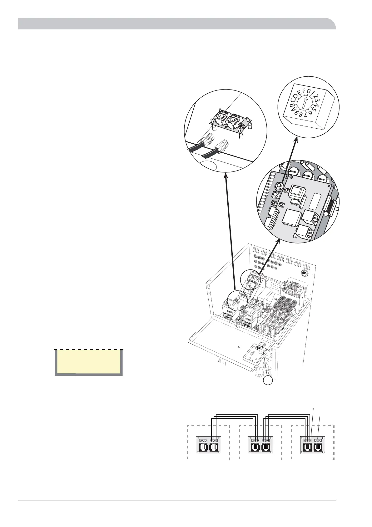
1. Check that the heat pump is switched off. Disconnect
the communication between the heat pumps. The
easiest way to do this is to temporarily disconnect the
modular cables from the communications card. (fig. 1)
2. Set the power switch (8) in position “1”.
3. Wait approximately 30 seconds.
4. Turn the selector switch marked U6 (fig. 4) on the
Measure card using a small screwdriver so that the
arrow points to the required position. 0 refers to a
Master while 1 – 8 refers to Slave 1 – 8. Each Slave is
given a unique address for communication with the
Master unit.
5. Wait approximately 5 seconds and check that the dis-
play shows your selection.
Example
6. Shut down the heat pump by turning the power switch
(8) to “0”. The heat pump is now configured to act ac-
cording to the setting.
7. Reconnect the modular cables that were disconnected
in step 1.
Connection of Master/Slave
Daisy-chain the heat pumps by using a screened 3-core
cable. Position A on terminal block X4 Cable on the com-
munications card (3) should be connected to position A on
terminal block X3 Cable on the communications card in
the next heat pump. In the same way, position B and GND
are connected together with the communications card in
the next heat pump.
Slave 1
1
MASTER
SLAVE 1SLAVE 2
X3 Cable
X4 Cable
4
U6
8
The heat pump in the picture is fitted with accessories.
 Loading...


