38 NIBE F1330
Installation / Adjustment
Description of functions - Expansion card 11
Sub shunt
A shunt valve (SV-V2) and a circulation pump (VBP4) can
be connected to a second heating circuit with a lower
temperature requirement.
The circulation pumps for heating circuits 1 and 2 (VBP3
and VBP4) are controlled together. These are activated in
standby mode.
The flow temperature is controlled via the shunt valve’s
increase/decrease signal and the sensor FS2.
The possibility to set the period and pulse times for the
shunt are located in menus 3.8 and 3.9.
The calculation of the flow temperature is done in the
same way and with the same type of settings as for
heating circuit 1.
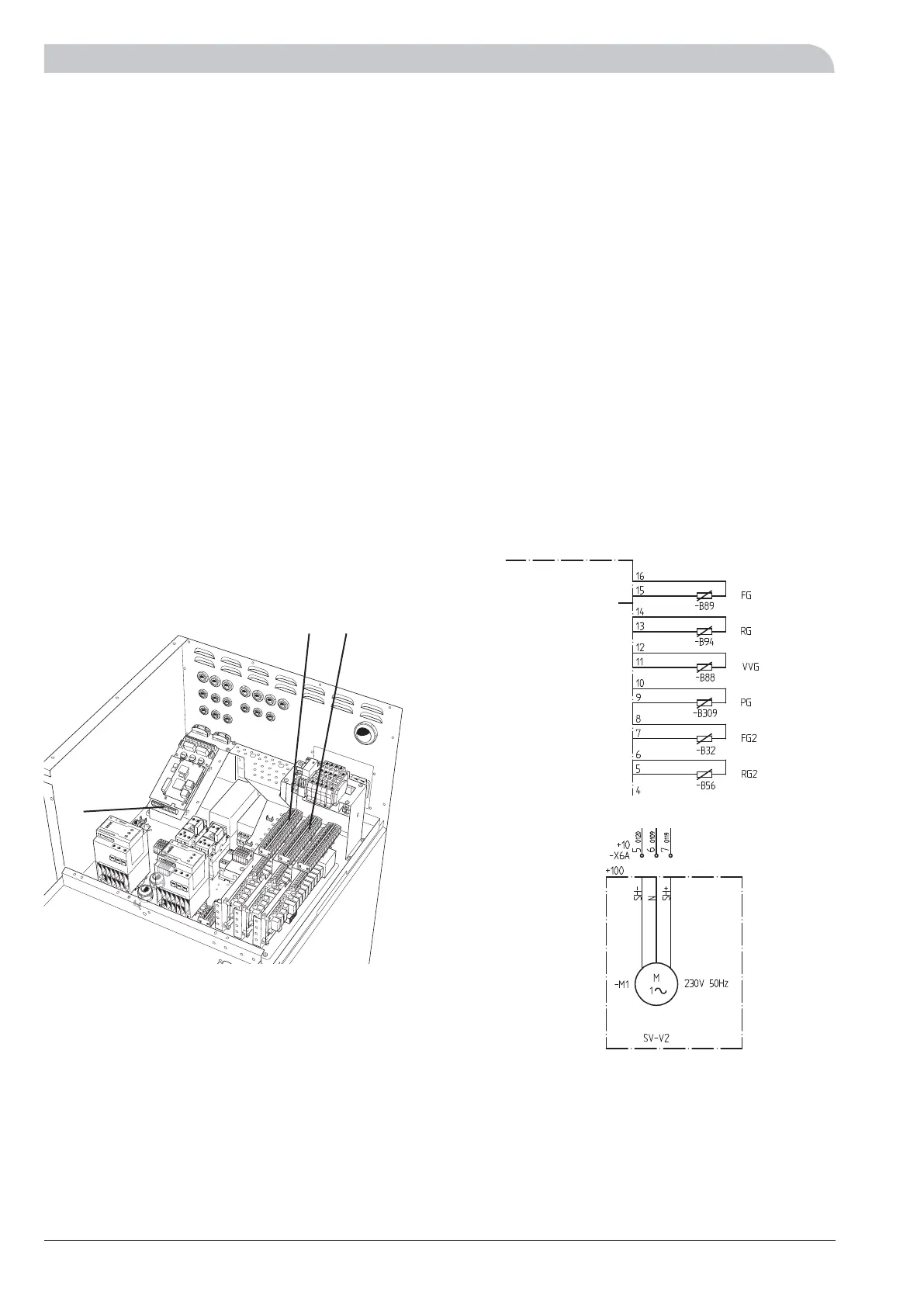
Connection of the sub shunt
The flow line sensor 2 (FS2) is fitted on the flow line to-
wards heating circuit 2. The sensor must make good con-
tact with the measurement area to give the best function.
When a submerged tube is not available, use the supplied
copper tube. The sensor is connected to screw terminals
X4:7 and X4:8 on the EBV-card”.
Return sensor 2 (RG2) must be installed on the return line
for heating circuit 2. The sensor must make good contact
with the measuring point and be well insulated for opti-
mum function. The sensor is connected to screw terminals
X4:5 and X4:6 on the “EBV card”.
The pump’s (VBP4) control signal is connected to the termi-
nal blocks X6:1 (230 V), X6:2 (N), i. e. same connection as
VBP3.
The shunt valve (SV-V2) is connected to the terminal blocks
X6A:5 (230 V decrease signal), X6A:6 (N) and X6A:7
(230 V increase signal).
Note that F1330 delivers 230 V control signals intend-
ed to control external contactors and not to drive
pumps.
LEK
+EBV-card
X4
X6 X6A
X4
The heat pump in the picture is fitted with accessories.
 Loading...


