28 NIBE F1330
Installation / Adjustment
Description of functions - Basic functions
Oil boiler
The oil burner is controlled by a relay (ETS-3/OP) and the
shunt valve’s (SV-P) increase/decrease signals using 2 relays.
A boiler sensor (PG) should also be installed.
When the degree-minute setting is reached the oil burner
starts. When the temperature reaches the required tem-
perature on the boiler sensor (PG), the shunt starts to
regulate with increase and decrease pulses after the set
period and pulse times. When the temperature in the
boiler is below the set temperature, the shunt valve moves
towards the closed position.
In standby mode the output ETS-3/OP (Base card) is volt-
age fed and with that, F1330 requests the oil boiler.
However, the boiler shunt (SV-P) must be controlled manu-
ally in standby mode.
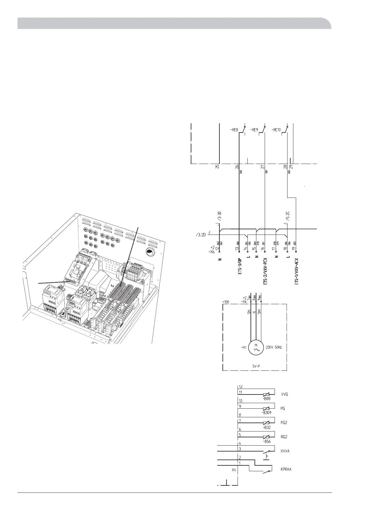
Connection of oil boiler
ETS-3/OP is connected to terminal blocks X6:12 (N) and
X6:13 (230 V with activation).
The shunt valve (SV-P) is connected to the terminal blocks
X6:7 (decrease signal), X6:8 (N) and X6:9 (increase signal).
The boiler sensor (PG) is fitted in the top of the boiler. The
sensor must make good contact with the measurement
area to give the best function. The sensor is connected to
screw terminals X4:9 and X4:10 on the EBV-card.
LEK
X6
X4
The heat pump in the picture is fitted with accessories.
+Base card
+EBV-card
 Loading...


