90
Alarm Hysteresis Section 4-2
a. Lower-limit temperature input shift value
b. Upper-limit temperature input shift value
3. After setting the calculated values to insl and insh, check the Digital
Controller readout (A) and thermometer temperature (B).
4. Here, offsets are set at two points, near room temperature and near the set
point. To improve accuracy within the measurement temperature range,
another point in the measurement temperature range other than the set
point should be set instead of room temperature.
Example of a 2-point
Temperature Input
Shift
In this example, a K thermocouple from −200.0 to 1,300.0°C is used. In equa-
tions 1 and 2, the set temperature lower limit YL is −200°C and the set tem-
perature upper limit YH is 1,300°C. Check the temperature of the control
target.
The temperature input offset values can be calculated as shown below when
the Digital Controller readout Y1 is 35°C for a room temperature X1 of 25°C
and when the Digital Controller readout Y2 is 105°C for a set point tempera-
ture X2 of 110°C.
Lower-limit Temperature Input Shift Value
Upper-limit Temperature Input Shift Value
4-2 Alarm Hysteresis
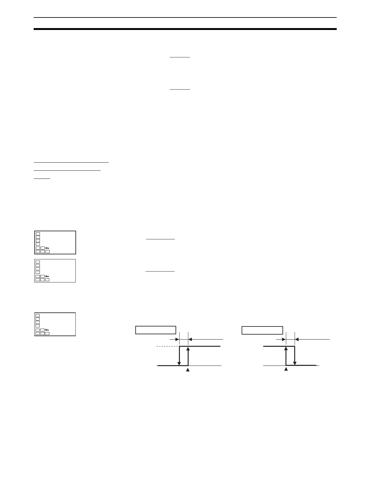
• The hysteresis of alarm outputs when alarms are switched ON/OFF can
be set as follows:
• Alarm hysteresis is set independently for each alarm in the Alarm Hyster-
esis 1 to Alarm Hysteresis 3 parameters (initial setting level).
• The default is 0.2 (°C/°F) when a temperature input is selected, and
0.02% FS when an analog input is selected.
4-2-1 Standby Sequence
• The standby sequence can be used so that an alarm will not be output
until the process value leaves the alarm range once and then enters it
again.
insl =
YL − Y1
Y2 − Y1
× {(X2 − Y2) − (X1 − Y1)} + (X1 − Y1)
insh =
YH − Y1
Y2 − Y1
× {(X2 − Y2) − (X1 − Y1)} + (X1 − Y1)
C
insl
-27.3
Lower-limit
Temperature
Input Shift
Value
insl =
−200 − 35
105 − 35
× {(110 − 105) − (25 − 35)} + (25 − 35) = −60.35 (°C)
C
insh
261.07
Upper-limit
Temperature
Input Shift
Value
C
insl
-60.35
Lower-limit
Temperature
Input Shift
Value
insh =
1300 − 35
105 − 35
× {(110 − 105) − (25 − 35)} + (25 − 35) = 261.07 (°C)
ON
OFF
ON
OFF
Upper-limit alarm
Alarm hysteresis
Alarm value
Lower-limit alarm
Alarm hysteresi
Alarm value

 Loading...


