60
Determining PID Constants (AT, ST, Manual Setup) Section 3-8
3-8 Determining PID Constants (AT, ST, Manual Setup)
3-8-1 AT (Auto-tuning)
• When AT is executed, the optimum PID constants for the set point at that
time are set automatically. A method (called the limit cycle method) for
forcibly changing the manipulated variable and finding the characteristics
of the control object is employed.
• Either 40% AT or 100% AT can be selected depending on the width of MV
variation in the limit cycle. In the AT Execute/Cancel parameter, specify
at-2 (100% AT) or at-1 (40% AT). To cancel AT, specify off (AT can-
cel).
• Only 100% AT can be executed for heating and cooling control or for float-
ing control for position-proportional models.
• AT cannot be executed when control has stopped or during ON/OFF con-
trol.
• The results of AT are reflected in the Proportional Band (P), Integral Time
(I), and Derivative Time (D) parameters for the PID set at the time AT exe-
cution starts. For details on PID sets, refer to PID Sets on page 129.
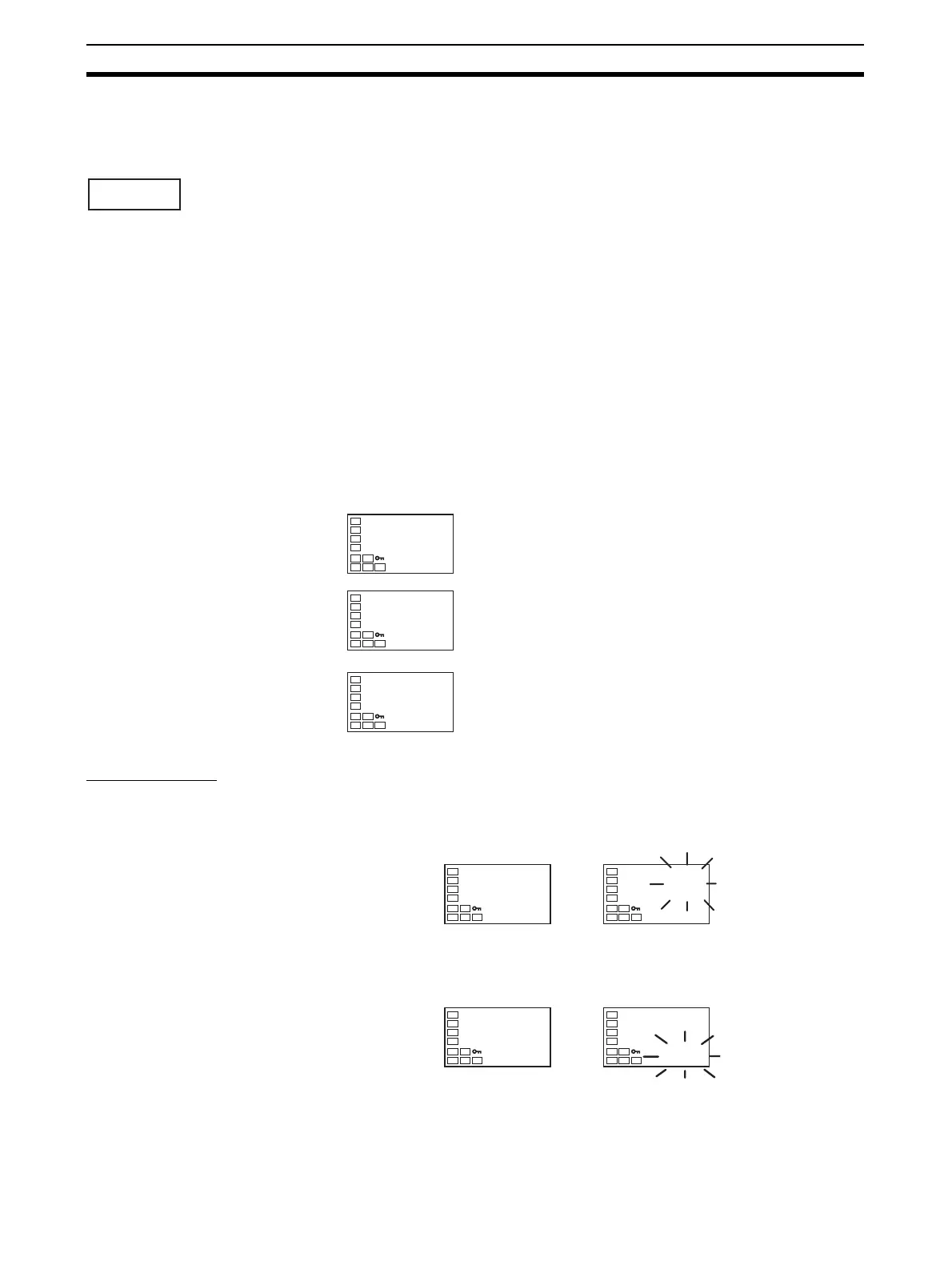
AT Operations AT is started when either at-2 (100% AT) or at-1 (40% AT) is specified for
the AT Execute/Cancel parameter. During execution, the AT Execute/Cancel
parameter on the No. 1 display flashes. When AT ends, the AT Execute/Can-
cel parameter turns OFF, and the No. 1 display stops flashing.
If you move to the operation level during AT execution, the No. 2 display
flashes to indicate that AT is being executed.
Only the Communications Writing, RUN/STOP, AT Execution/Cancel, and Pro-
gram Start parameters can be changed during AT execution. Other parame-
ters cannot be changed.
at
∗
.i
233.0
C
∗
.p
(0
∗
.d
40.0
PID Setting Level
PID* Proportional Band
PID* Integral Time
PID* Derivative Time
(
∗
: 1 to 8)
at
off
at
at-2
AT Execute/Cancel
No. 1 displa
100% AT execution in progress
C
25.0
100.0
C
25.0
100.0
PV/SP
AT execution in progress
No. 2 display

 Loading...


