110
PV Change Color Section 4-10
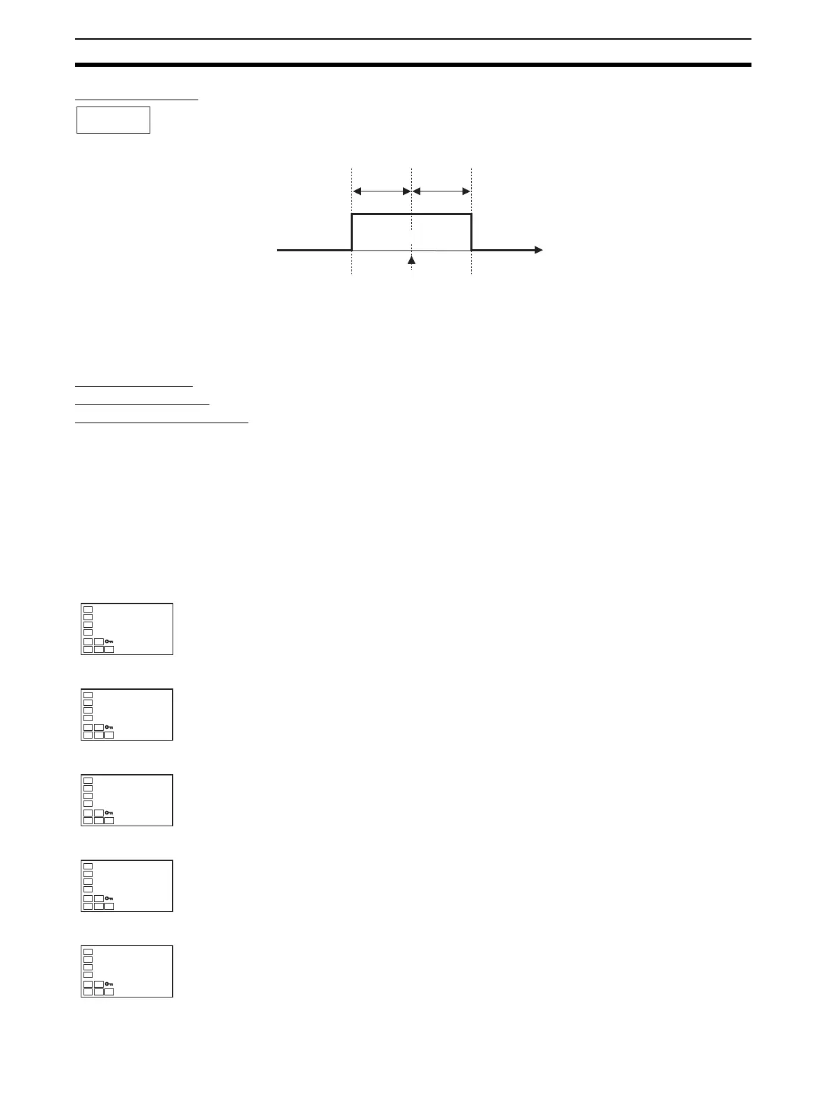
PV Stable Band When the mode to link to the PV stable band is selected, the PV display color
will change according to whether the present value (PV) is lower than, within,
or higher than the PV stable band shown in the following figure. The PV stable
band is set with the SP as the center, as shown below.
The default is 5.0 (°C/°F) for a temperature input and 5.0% FS for an analog
input.
4-10-2 Setting
Setting the PV
Change Color to
Indicate Stable Status
To display the PV in a stable green display when the PV is within ±15.0°C of
the set point to enable checking the control process at a glance, set the PV
Change Color and PV Stable Band parameters.
PV change color = r-gr (Red to Green to Red)
PV stable band = 15.0°C
Operating Procedure Release the protection before setting the PV Change Color and PV Stable
Band parameters to enable moving to advanced function setting level. (Refer
to steps 1 to 8 on page 104.)
PV Change Color: r-g.r (Red to Green to Red)
PV Stable Band: 15.0 (°C)
pv-b
PV Stable
Band
P
SP
PV stable
band
PV stable
band
Low Within High
Operation Level
Initial Setting Level
1. Press the O Key for at least three seconds to move from the operation
level to the initial setting level.
Initial Setting Level
2. Select the Move to Advanced Function Setting Level parameter by press-
ing the M Key.
3. Use the D Key to enter “−169” (the password).
Advanced Function Setting Level
Move to the advanced function setting level by pressing the M Key or
leaving the setting for at least two seconds.
Advanced Function Setting Level
4. Select the PV Change Color parameter by pressing the M Key.
C
25.0
100.0
PV/S
in-t
5
Input Type
amov
-169
Move to Ad-
vanced Function
Setting Level
init
off
Parameter
Initialization
colr
red
PV Change
Color

 Loading...


