30
Wiring Terminals Section 2-2
2-2-2 Precautions when Wiring
• Separate input leads and power lines in order to prevent external noise.
• Use AWG24 (cross-sectional area: 0.205 mm
2
) to AWG14 (cross-sec-
tional area: 2.081 mm
2
) twisted-pair cable (stripping length: 5 to 6 mm).
• Use crimp terminals when wiring the terminals.
• Use the suitable wiring material and crimp tools for crimp terminals.
• Tighten the terminal screws to a torque of 0.74 to 0.90 N·m.
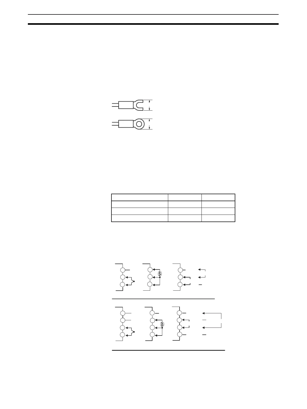
• Use the following types of crimp terminals for M3.5 screws.
Note Do not remove the terminal block. Doing so will result in malfunction or failure.
2-2-3 Wiring
In the connection diagrams, the left side of the terminal numbers represents
the inside of the Controller and the right side represents the outside.
Power supply • With the E5CN-H, connect to terminals 9 and 10; with the E5AN-H and
E5EN-H, connect pins 1 and 2. The following table shows the specifica-
tions.
• These models have reinforced insulation between the input power supply,
the relay outputs, and other terminals.
Input • Make the connections as shown below, using terminals 3 to 5 for the
E5CN-H and pins 17 to 20 for the E5AN/EN-H, and matching the input
types.
Note When wiring a voltage input, check the connected terminals care-
fully to make sure there are no mistakes. Incorrect wiring can cause
the Unit to fail.
7.2 mm max.
7.2 mm max.
Input power supply E5CN-H E5AN/EN-H
100 to 240 VAC, 50/60 Hz 8.5 VA 12 VA
24 VAC, 50/60 Hz 5.5 VA 8.5 VA
24 VDC (no polarity) 3.5 W 5.5 W
E5CN-H
Do not
use.
18
17
+
−
−
+
+
mA
−
−
+
−
V
+
−
V
+
Platinum resistance
thermometer
Thermocouple
Analog input
E5AN/EN-H
Analog input
Platinum resistance
thermometer
Thermocouple
Do not
use.
Do not
use.
Do not
use.
Do not
use.
Do not
use.
Do not
use.
Do not
use.
17 17
18
18
19
20
19
20
19
20
4
3
5
4
3
5
4
3
5
mA
Do not
use.
Do not
use.

 Loading...


