91
Alarm Hysteresis Section 4-2
• For example, with a lower limit alarm, the process value will normally be
below the set point, i.e., within the alarm range, when the power supply is
turned ON, causing an alarm to be output.
If the lower limit alarm with a standby sequence is selected, an alarm will
not be output until the process value increases above the alarm set value,
i.e., until it leaves the alarm range, and then falls back below the alarm set
value.
Restart • The standby sequence is canceled when an alarm is output. It is, how-
ever, restarted later by the Standby Sequence Reset parameter
(advanced function setting level). For details, refer to the Standby
Sequence Reset parameter in SECTION 5 Parameters.
4-2-2 Alarm Latch
• The alarm latch can be used to keep the alarm output ON until the latch is
canceled regardless of the temperature once the alarm output has turned
ON.
Any of the following methods can be used to clear the alarm latch.
• Turn OFF the power supply. (The alarm latch is also cleared by switching
to the initial setting level, communications setting level, advanced function
setting level, or calibration level.)
•Use the PF Key.
• Use an event input.
For details on setting the PF Key, refer to 4-20 Setting the PF Key. For details
on setting events, refer to 4-5 Using Event Inputs.
Summary of Alarm
Operation
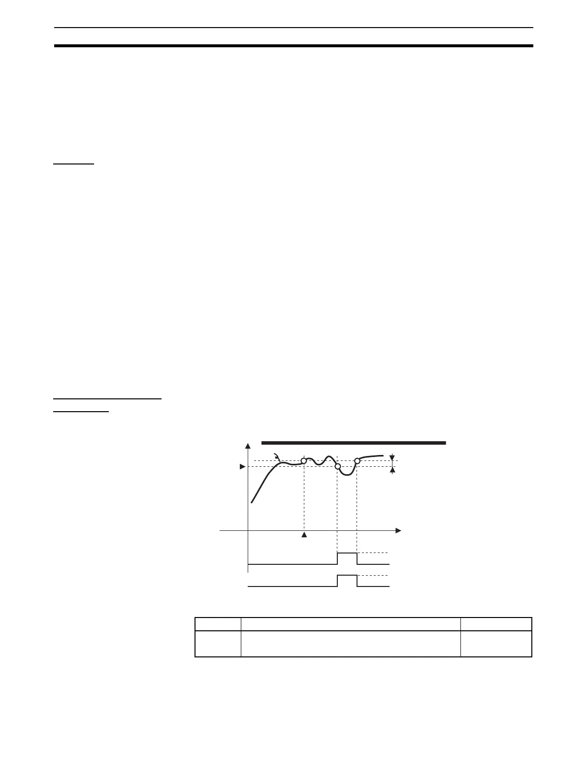
The following figure summarizes the operation of alarms when the Alarm Type
parameter is set to “lower-limit alarm with standby sequence” and “close in
alarm” is set.
Parameters
Note * = 1 to 3
OFF
ON
PV
Alarm type: Lower-limit alarm with standby sequence
Alarm value
Alarm hysteresis
Time
Standby sequence
canceled
Alarm
Output
OFF
o
en
ON (closed)
Symbol Parameter: level Description
alh*
rest
Alarm 1 to 3 Hysteresis: Initial setting level
Standby Sequence: Advanced function setting level
Alarm
Alarm

 Loading...


