284
Parameter Structure
Section 6-1
6-1 Parameter Structure
• To execute user calibration, enter the password “1201” at the Move to Cal-
ibration Level parameter in the advanced function setting level. The mode
will be changed to the calibration mode, and adj will be displayed.
• The Move to Calibration Level parameter may not be displayed. If this
happens, set the Initial/Communications Protect parameter in the protect
level to 0 before moving to the advanced function setting level. (The
default setting is 0.)
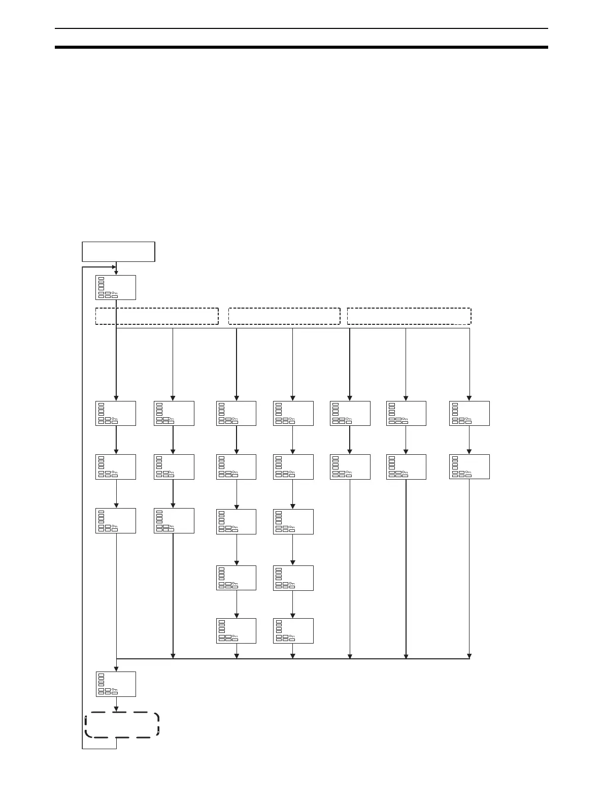
• The calibration mode is ended by turning the power OFF.
• The parameter calibrations in the calibration mode are structured as
shown below.
Controllers with Thermocouple/Resistance Thermometer Universal Inputs
21: K
22: J
23: T
5: K
7: J
11: E
12: L
15: N
19: W
20: PLII
6: K
8: J
9, 10: T
13, 14: U
16: R
17: S
18: B
1: Pt100
2: Pt100
3: JPt100
4: JPt100
24: Pt100
0: Pt100 25: 4 to 20 mA
26: 0 to 20 mA
27: 1 to 5 V
28: 0 to 5 V
29: 0 to 10
Advanced Function
Setting Level
Moves automatically according to input type.
Platinum resistance thermometer
Thermocouple
Note: This is displayed only for Controllers that have a transfer
output (E5AN/EN-H@@F).
adj
30
p390
e20c
p280
e26b
t 54
b9a5
t 24
e220
a 20
c8e7
a 1
4677
t -6
0200
t -6
2988
p 10
4543
p 10
4543
c400
29be
c700
ba13
c400
29be
c700
ba13
str
no
bia5
35b8
bia5
35b8
p200
93a7
p140
93d7
1v 5
c7c3
1v 1
5ac0
2v10
b104
2v 1
4ad9
Analog input
Transfer Output
Calibration

 Loading...


