Startup Procedure and
Test Run
4
4.2 Component Names and Functions
SIEPYEUOQ2A01A AC Drive Q2A Technical Manual 121
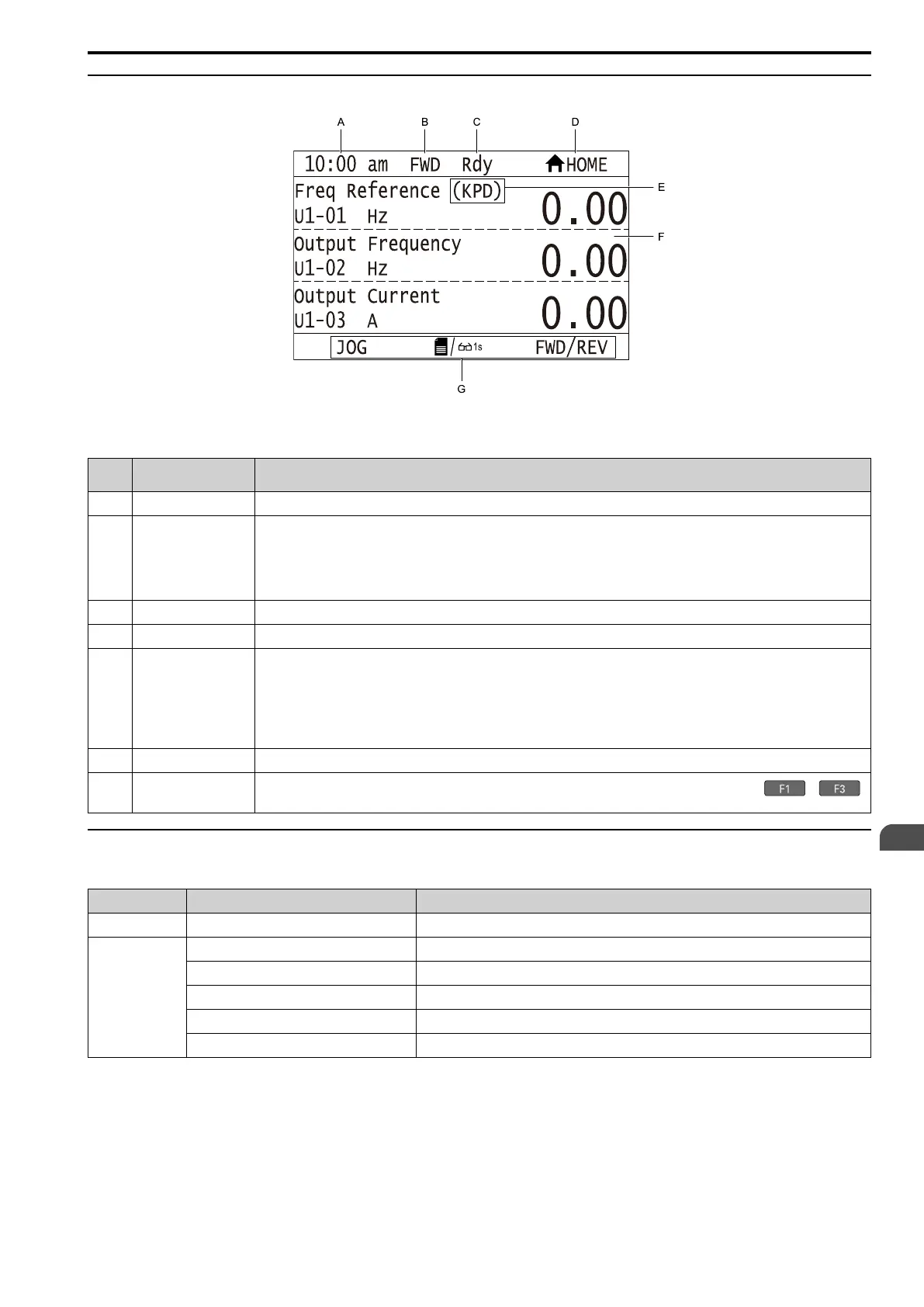
◆ Operator Display
Figure 4.4 Operator Display Indications
Table 4.2 Operator Display Indications and Meanings
Sym
bol
Name Description
A Time display area
Shows the current time. Set the time on the default settings screen.
B
Forward run/Reverse run
indication
Shows direction of motor rotation.
• FWD: Shown when set to Forward run.
• REV: Shown when set to Reverse run.
Note:
In Q2pack operation, FWD or REV flash.
C
Ready
The screen will show Rdy when the drive is ready for operation or when the drive is running.
D Mode display area
Shows the name of the current mode or screen.
E
Frequency reference
source indicator
Shows the current frequency reference source.
• KPD: keypad
• AI: analog input terminal (terminals AI1 to AI3)
• COM: Modbus communications
• OPT: option card
• PI: pulse train input terminal (terminal PI)
F Data display area
Shows parameter values, monitor values, and details of the results of operations.
G
Function keys 1 to 3 (F1
to F3)
The function names shown in this area will change when the selected screen changes. Push one of the function keys to
on the keypad to do the function.
◆ Keypad Mode and Menu Displays
Table 4.3 Drive Mode, Menu Screens and Functions
Mode Menu Screen Function
Drive Mode Monitor & Diagnostics
Shows drive monitors, Custom Monitors, Fault Log, Data Logger.
Programming Mode
Parameters
Changes parameter settings.
Modified Parameters
Shows standard and Q2pack related modified parameters.
Manual Setup
Holds a list of user-set parameters and monitors.
Wizard & Autotuning
Calls Setup Wizards for easy commissioning or Auto-Tuning.
Configuration
Sets language, date/time, backlight, parameter backup function.
 Loading...