Parameter List
11
11.3 b: APPLICATION
SIEPYEUOQ2A01A AC Drive Q2A Technical Manual 401
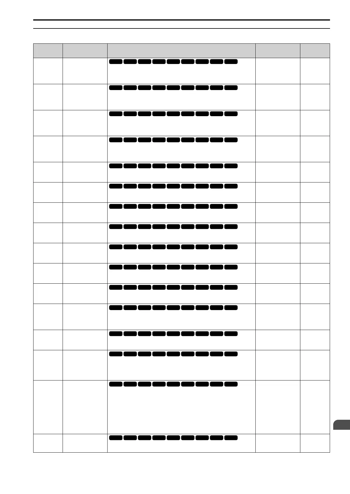
◆ b5: PID CONTROL
No.
(Hex.)
Name Description
Default
(Range)
Ref.
b5-01
(01A5)
PID Enable
Enables PID control.
0 : Disabled
1 : Enabled
0
(0,1)
545
b5-70
(01E5)
PID MainRefMode
Sets the PID main reference mode.
0 : PID only
1 : Fref + PID
0
(0, 1)
545
b5-71
(01E6)
PID Fdbk 1/2 Selection
Selects the feedback configuration for PID control.
0 : Feedback 1
1 : Feedback 2
0
(0, 1)
545
b5-72
(01E7)
PID D-FF Mode
Determines whether the D part is in the feedback path or used for feed forward control.
0 : D=Fdback
1 : D=FdFwd
0
(0, 1)
546
b5-02
(01A6)
RUN
Proportional Gain (P)
Sets the proportional gain (P) that is applied to PID input.
1.00
(0.00 - 25.00)
546
b5-03
(01A7)
RUN
Integral Time (I)
Sets the integral time (I) that is applied to PID input.
1.0 s
(0.0 - 360.0 s)
546
b5-04
(01A8)
RUN
Integral Limit
Sets the upper limit for I control as a percentage of E1-04 [Max Output Frequency].
100.0%
(0.0 - 100.0%)
546
b5-05
(01A9)
RUN
Derivative Time (D)
Sets the derivative time (D) for PID control. This parameter adjusts system
responsiveness.
0.00 s
(0.00 - 10.00 s)
547
b5-06
(01AA)
RUN
PID Output Limit
Sets the maximum possible output from the PID controller as a percentage of E1-04
[Max Output Frequency].
100.0%
(0.0 - 100.0%)
547
b5-07
(01AB)
RUN
PID Offset Adjustment
Sets the offset for the PID control output as a percentage of E1-04 [Max Output
Frequency].
0.0%
(-100.0 - +100.0%)
547
b5-08
(01AC)
Expert
PID Primary Delay Time
Constant
Sets the primary delay time constant for the PID control output. Usually it is not
necessary to change this setting.
0.00 s
(0.00 - 10.00 s)
547
b5-09
(01AD)
PID Output Level
Selection
Sets the polarity of the PID output.
0 : Normal output
1 : Reverse output
0
(0, 1)
547
b5-10
(01AE)
RUN
PID Output Gain Setting
Sets the amount of gain to apply to the PID output.
1.00
(0.00 - 25.00)
547
b5-11
(01AF)
PID Output Reverse
Selection
Sets the function that enables and disables reverse motor rotation for negative PID
control output.
0 : 0 lower limit
1 : Negative lower limit
0
(0, 1)
548
b5-12
(01B0)
Fdback Loss Select
Mode
Sets the drive response to PID feedback loss. Sets drive operation after the drive detects
PID feedback loss.
0 : DO Only Always
1 : AL+DO Always
2 : FLT+DO Always
3 : DO Only@PID Enable
4 : AL+DO@PID Enable
5 : FLT+DO@PID Enable
0
(0 - 5)
548
b5-13
(01B1)
Fdback Loss Lvl
Sets the level that triggers PID Feedback Loss [FbL] as a percentage of E1-04 [Max
Output Frequency].
0%
(0 - 100%)
549

 Loading...


