Modbus Communication 12-9
AC10 Inverter
12.8 Physical Interface
12.8.1 Interface instruction
Communication interface of RS485 is located on the most left of control terminals, marked
underneath with A+ and B-
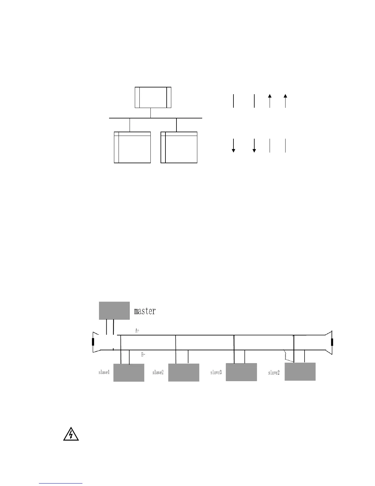
12.8.2 Structure of Field Bus
Connecting Diagram of Field Bus
RS485 Half-duplex communication mode is adopted for AC10 series inverter. Daisy chain
structure is adopted by 485 Bus-line. Do not use 'spur' lines or a star configuration. Reflect
signals which are produced by spur lines or star configuration will interfere in 485
communications.
Note that for the same time in half-duplex connection; only one inverter can have
communication with PC/PLC. Should two or more than two inverters upload data at the same
time, then bus competition will occur, which will not only lead to communication failure, but
higher current to certain elements as well.
12.9 Grounding and Terminal
Terminal resistance of 120
will be adopted for terminal of RS485 network, to diminish the
reflection of signals. Terminal resistance shall not be used for intermediate network.
No direct grounding shall be allowed for any point of RS485 network. All the equipment in the
network shall be well grounded via their own grounding terminal. Please note that grounding
wires will not form closed loop in any case.
Connecting Diagram of Terminal Resistance
Check the drive capacity of PC/PLC and the distance between PC/PLC and inverter when
wiring. Add a repeaters if drive capacity is not enough.
All wiring connections for installation shall have to be made when the inverter is disconnected
from power supply.

 Loading...


