’s value: 10
When multi-stage speed terminal is set to free stop terminal (8) and external coast stop terminal
(9), terminal logic level is set by this group of function codes. When F324=0 and F325=0,
positive logic and low level is valid, when F324=1 and F325=1, negative logic and high level is
valid.
F330 Diagnostics of DIX terminal Only read
F330 is used to display the diagnostics of DIX terminals.
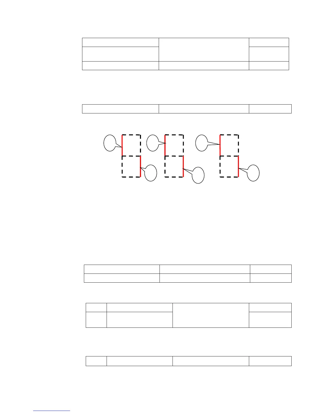
Please refer to Figure 9-7 about the DIX terminals diagnostics in the first digit.
Figure 9-7 Status of digital input terminal
The dotted line means this part of digitron is red.
For example, in the first digitron, the upper part of digitron is red, it means DI1 terminal is invalid.
The lower part of digitron is red, it means DI2 is valid. The three digitrons stands for the status
of DI1-DI6 terminals
In four-line LCD, please set F645=22 at first, after pressing FUN key, the displayed interface
can be switched into eight 0. They are used to display the DI terminal status. If DIX is
connected to CM, and 0 changes to 1, it means the DIX terminal is valid.
9.3.3 Analog input monitoring
T
The value of analog is displayed by 0~4095.
F335 Relay output simulation Setting range:
0:Output active
1:Output inactive.
Mfr’s value: 0
F336 DO1 output simulation Mfr’s value: 0
Take an example of DO1 output simulation, when inverter is in the stop status and enter F336,
press the UP key, the DO1 terminal is valid. Relax the UP key, DO1 remains valid status. After
quitting F336, DO1 will revert to initial output status.
F338 AO1 output simulation
Setting range: 0~4095
Mfr’s value: 0
When inverter is in the stop status, and enter F338 or F339, press the UP key, the output
analog will increase, and when press the DOWN key, the output analog will decrease. After
quitting the parameters, AO1 and AO2 will revert to initial output status.
F331Monitoring AI1 Only read
F332 Monitoring AI2 Only read

 Loading...


