Installation & Connection 7-5
AC10 Inverter
7.4 Functions of Control Terminals
To operate the inverter the user must operate the control terminals correctly and flexibly. The
following is a description of the user terminals and any relevant parameters.
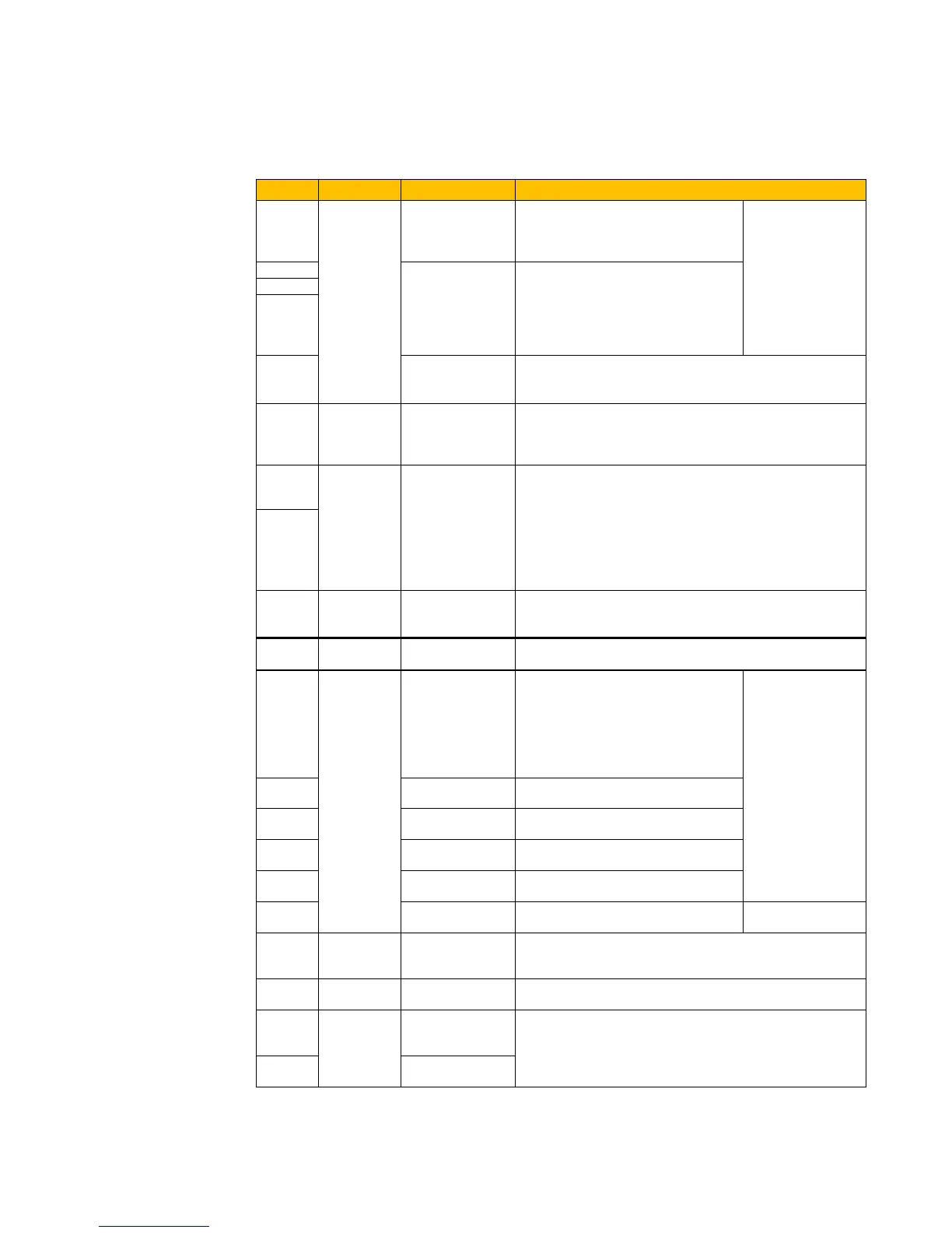
Table 7-3 Functions of Control Terminals
DO1
Output
signal
Multifunctional
output terminal 1
When the token function is valid, the
value between this terminal and CM
is 0V; when the inverter is stopped,
The functions of
output terminals
manufacturer’s
value. Their initial
state may be
changed through
changing function
codes.
TC is a common point, TB-TC are
normally closed contacts, TA-TC are
normally open contacts. The contact
capacity of 15kW and below 15kW
inverter is 10A/125VAC、5A/250VAC、
It is connected with frequency meter, speedometer or
ammeter externally, and its minus pole is connected with
10V
Analog
power
supply
Self contained
power supply
Internal 10V self-contained power supply of the inverter
provides power to the inverter. When used externally, it can
only be used as the power supply for voltage control signal,
with current restricted below 20mA.
AI1
Input
Signal
Voltage / Current
analog input
When analog speed control is selected, the voltage or
current signal is input through this terminal. The range of
voltage input is 0~5V or 0~10V and the current input is 0~
20mA, the input resistor is 500Ohm, and grounding: GND.
If the input is 4~20mA, it ca
n be realized through adjusting
parameter F406. The voltage or current signal can be
chosen by coding switch. See table 7-2 for details, the
current channel (0-20mA) is chosen before delivery.
Ground terminal of external control signal (voltage control
signal or current source control signal) is also the ground of
10V power supply of this inverter.
Power: 24±1.5V, grounding is CM; current is restricted
below 50mA for external use.
control
terminal
Jogging terminal
When this terminal is valid, the
inverter will have jogging running.
The jogging function of this terminal is
valid under both at stopped and
running status. This terminal can also
be used as high-speed pulse input
port. The max frequency is 50K.
The functions of
input terminals
manufacturer’s
value. Other
functions can also
be defined by
changing function
codes.
DI2
When this terminal is valid, “ESP”
malfunction signal will be displayed.
When this terminal is valid, inverter
will run forward.
When this terminal is valid, inverter
will run reverse.
Make this terminal valid under fault
status to reset the inverter.
Make this terminal valid during
running can realise free stop
The grounding of 24V power supply and othr control
signals.
+5V
Grounding for digital signal
A+
RS485
communicati
on terminals
Standard: TIA/EIA-485(RS-485)
Communication protocol: Modbus
Communication rate:
1200/2400/4800/9600/19200/38400/57600bps
B-
Negative polarity of
Differential signal
TC-Hydraulik - Rsdorfer Str. 8 - 25746 Heide - Lars Lornsen - T: +49 481 909 - 34 - l.lornsen@tc-hydraulik.de - www.tc-hydraulik.de

 Loading...


