7-8 Installation & Connection
AC10 Inverter
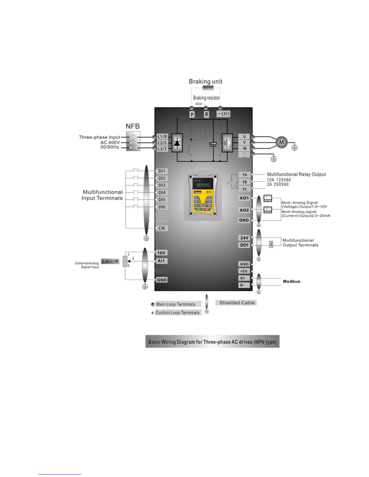
7.6 Connection Overview
Refer to next figure for the overall connection sketch for AC10 series IP66 inverters. Various
wiring modes are available for the terminals whereas not every terminal needs to be connected
in each mode when applied.
Note:
1. Please only connect power terminals L1 and L2 with power grid for single-phase inverters.
2. Remote-control panels are connected with 8 core telephone wire. 485 communication port is
on the control terminals.
3. 485 communication port has built-in standard MODBUS communication protocol. The
terminal sequence is GND, +5V, A+, B-.
4. Inverter has 6 multifunctional input terminals DI1~DI6.
5. The contact capacity of inverter is 10A/125VAC, 5A/250VAC and 5A/30VDC.

 Loading...


