7-6 Installation & Connection
AC10 Inverter
7.5 Wiring for Digital Input Terminals:
Generally, shielded cable is recommended and wiring distance should be as short as possible.
When the analogue reference signal is used, it is necessary to take filter measures to prevent
power supply interference.
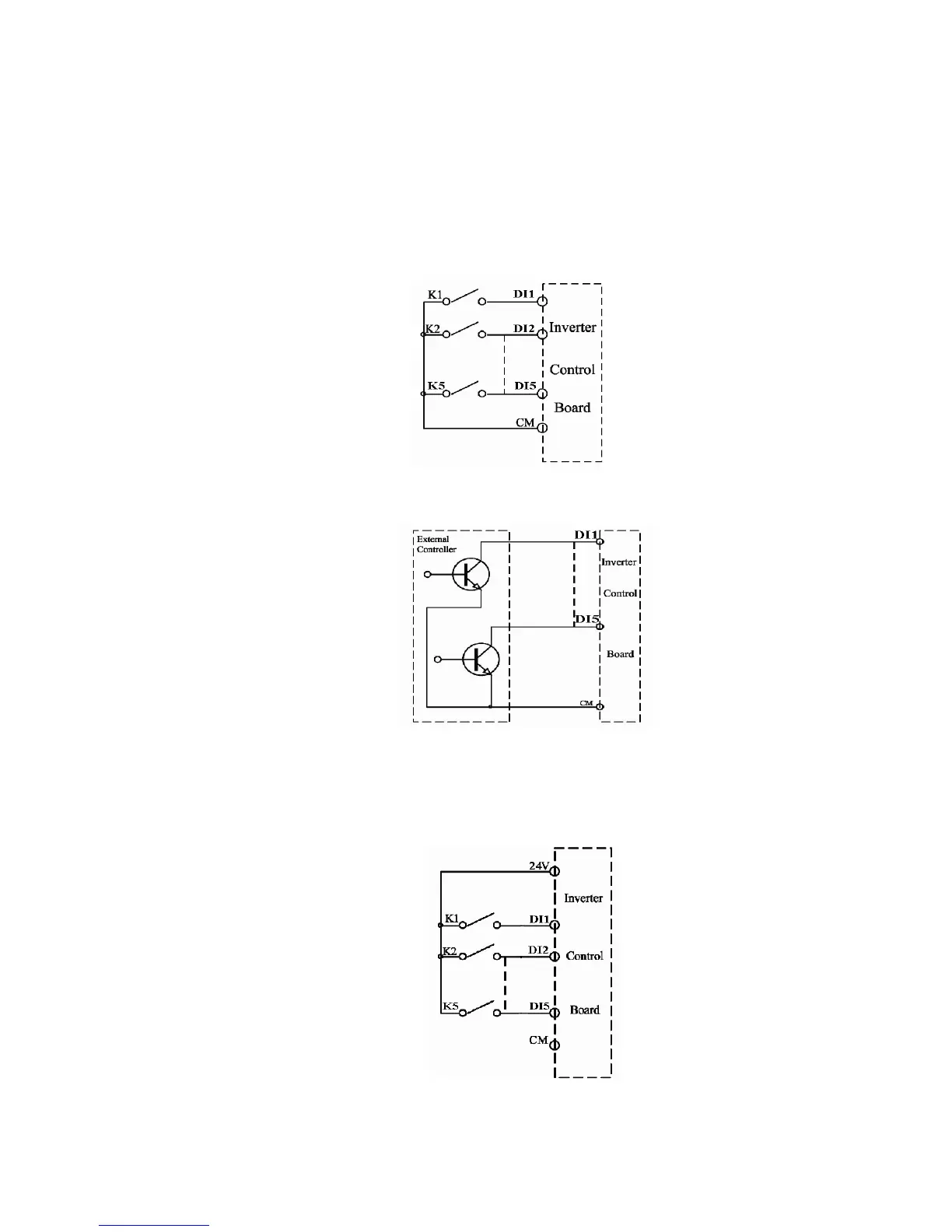
Digital input terminals are only connected by source electrode (NPN mode) or by sink electrode
(PNP mode). If NPN mode is adopted, please slide the toggle switch to the end of “NPN”.
Wiring for control terminals as follows:
7.5.1 Wiring for positive source electrode (NPN mode).
7.5.2 Wiring for active source electrode
If digital input control terminals are connected by sink electrode, slide the toggle switch to the
end of “PNP”. Wiring for control terminals as follows:
7.5.3 Wiring for positive Sink electrode (PNP mode)

 Loading...


