5-1 The Keypad
AC10 Inverter
Chapter 5 The Keypad
5.1 The Display
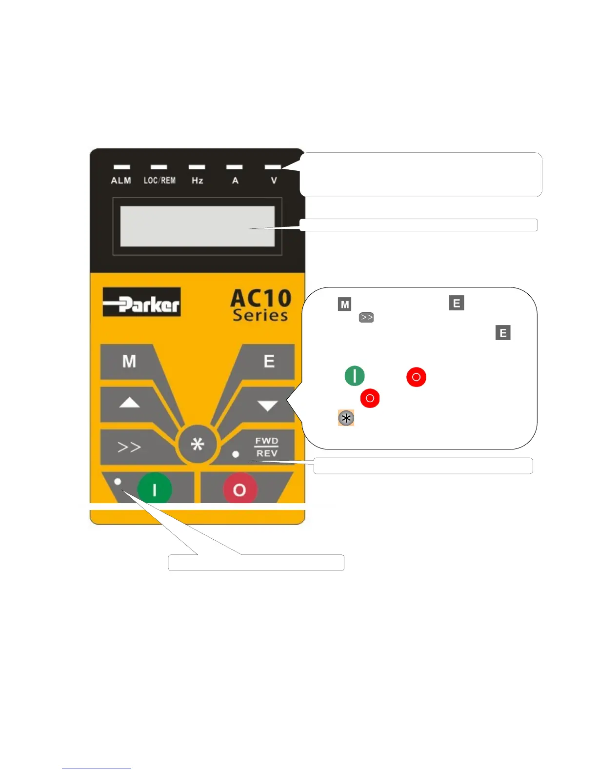
Keypad panel and monitor screen are both fixed on the keypad controller. See Figure 5-1
Keypad Displays.
Figure 5-1 Keypad Displays
5 indicators indicate working status. ALM is ON when
fault occurs. LOC/REM is ON in the remote-controlling
status. Hz is ON when frequency is shown, A is ON when
current is shown, and V is ON when voltage is shown.
for function code, and for original
, ▲ and ▼keys can be used to
select function codes and parameters. Press
again to confirm. In the mode of keypad control,
▼keys can also be used for dynamic speed
key and keys control start and
key to reset inverter in fault status.
P
ress Key to set Fwd/Rev jogging and select
The runnining indicator is ON whilte running.
TC-Hydraulik - Rsdorfer Str. 8 - 25746 Heide - Lars Lornsen - T: +49 481 909 - 34 - l.lornsen@tc-hydraulik.de - www.tc-hydraulik.de

 Loading...


