RAD-...-IFS
104 / 198
PHOENIX CONTACT 105542_en_05
7.4.3 Diagnostic LEDs
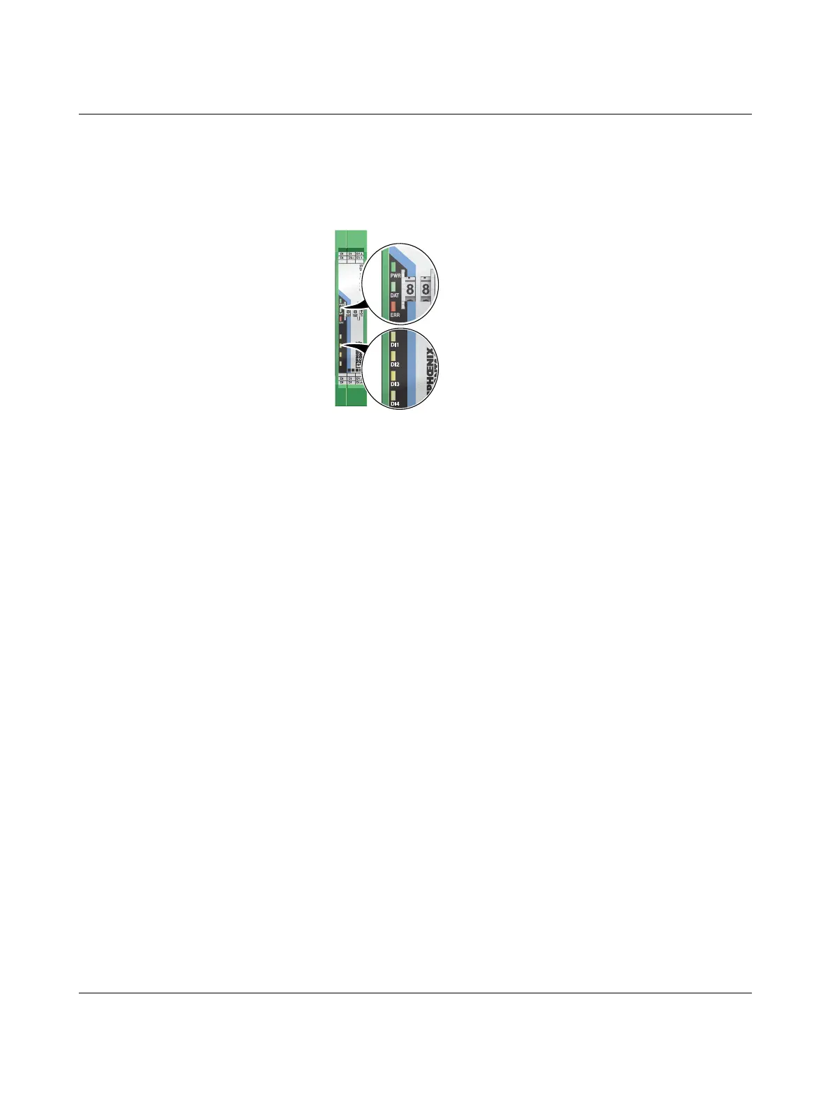
The RAD-DI4-IFS I/O extension module uses a total of seven LEDs to indicate the operating
states.
Figure 7-20 Diagnostic LEDs of the RAD-DI4-IFS
PWR LED
The green PWR LED indicates the status of the supply voltage.
DAT LED
The green DAT LED indicates the status of bus communication.
ERR LED
The red ERR LED indicates the error status, e.g., if a corresponding output module has not
been found.
DI1 ... DI4
The yellow DI1 ... DI4 LEDs indicate the state of the digital inputs.
Off No supply voltage
On Supply voltage OK
Off No communication
Flashing Configuration and addressing mode
On Cyclic data communication
Off No error
Flashing
Slow (1.4 Hz) I/O MAP address changed
Fast (2.8 Hz) No bus communication
On Critical internal error
DI1L DI1H DI1
DI2L DI2H DI2
DI3L DI3H DI3
DI4L DI4H DI4
PWR
DAT
ERR
4H4L
33H3L
1L 1H 1
2L 2
DI1
DI2
DI3
DI4

 Loading...

