Installation
105542_en_05 PHOENIX CONTACT 19 / 198
3 Installation
3.1 Wireless module structure
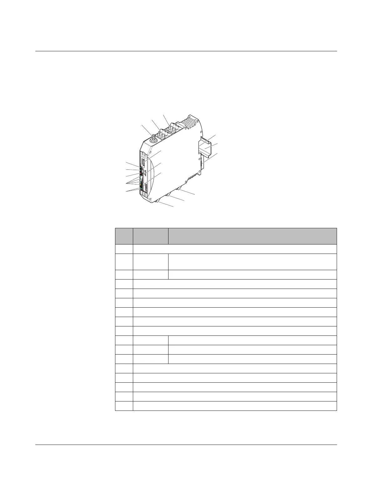
Figure 3-1 Wireless module structure
Item Ter m in al
block
Designation
1 RSMA antenna connection (socket)
2 2.1/2.2 RSSI test output (0 V ... 3 V DC) for evaluation of the wireless signal
strength
3 1.1/1.2 Device supply (+24 V DC, GND)
4 S-PORT (12-pos. programming interface)
5 Yellow thumbwheel for setting the RAD ID
6SET button
7 Connection option for DIN rail connector
8DIN rail
9 Metal foot catch for DIN rail fixing
10 4.1/4.2 Connection terminal blocks for RS-485 interface
11 5.1/5.2/5.3 Connection terminal blocks for RS-232 interface
12 6.1/6.2/6.3 Relay output with floating changeover contact (RF link relay)
13 Status LED (RX/TX) for RS-232/485 serial interface
14 LED bar graph for displaying the wireless signal strength
15 ERR status LED, red (communication error)
16 DAT status LED, green (bus communication)
17 PWR status LED, green (supply voltage)
+
2
4
V
R
S
S
I
+
R
S
S
I
-
A
N
T
C
O
M
1
N
O
1
N
C
1
R
X
T
X
G
N
D
D
(
A
)
D
(
B
)
Reset
RAD-ID
RAD-2400-IFS
S.PORT
8
8
PW
R
DA
T
ER
R
R
X
TX
0
V
+
2
4
V
0
V
R
S
S
I
+
R
S
S
I
-
2
1
3
4
5
7
6
9
11
12
17
16
13
15
14
10
8

 Loading...

