RAD-...-IFS
158 / 198
PHOENIX CONTACT 105542_en_05
• Connect terminal points 5.1 and 5.2 of the RS-232 interface on the slave module to be
tested.
Figure 9-1 Loopback test on an RS-232 interface
• Connect the two wireless modules to the power supply.
• Check the wireless connection via the LED bar graph.
• Enter several characters of your choice. HyperTerminal transmits these characters
over the wireless path. The characters are output on the slave side (e.g., at terminal
point 5.1, RX cable of the RS-232 interface) and immediately read again using the
bridge (e.g., at terminal point 5.2, TX cable of the RS-232 interface). This returns the
transmitted characters and they appear twice on the HyperTerminal screen.
– The screen remains blank if the check was not successful. Monitor the TX and RX
LEDs on every wireless module. In this way, you can determine the point up to
which data has been transmitted.
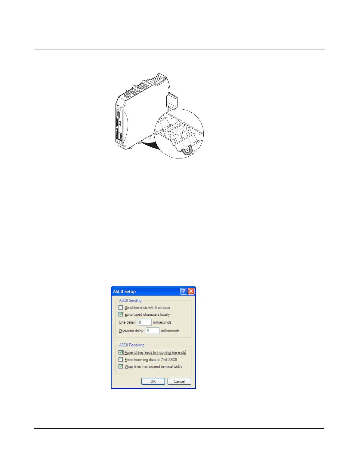
– If the characters only appear once, check the HyperTerminal settings for hidden
outgoing characters. The following options must be enabled under “File, Proper-
ties, Settings, ASCII Setup”:
“Echo typed characters locally” and
“Append line feeds to incoming line ends”
Figure 9-2 Settings in HyperTerminal
+24
V
R
SS
I+
R
SS
I-
A
NT
CO
M
1
NO
1
N
C
1
RX
TX
G
N
D
D(A) D
(B
)
Reset
RAD-ID
RAD-2400-IFS
S.PORT
8
8
P
W
R
D
A
T
E
R
R
R
X
T
X
0V
+24
V
0V
RS
SI+
R
S
SI-
5.1
5.2
5.3

 Loading...

