Description of I/O extension modules
105542_en_05 PHOENIX CONTACT 87 / 198
7 Description of I/O extension modules
7.1 RAD-AI4-IFS - analog extension module with four
inputs
The RAD-AI4-IFS analog I/O extension module can process up to four input signals with
0/4 mA ... 20 mA. All inputs are electrically isolated from one another, from the supply volt-
age, and from the electronics.
A supply voltage of at least 12 V DC is available at connection terminal block PWR
1
for pas-
sive sensors (see Figure 7-1, item 1).
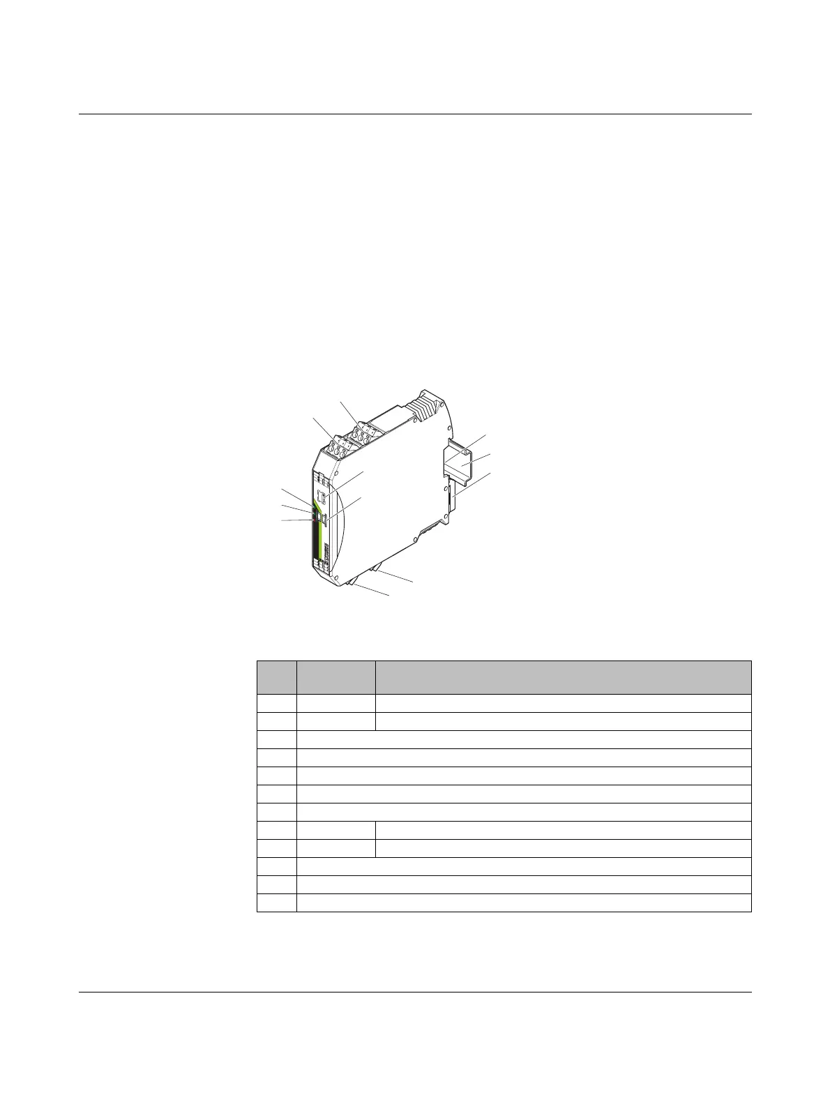
7.1.1 Structure
Figure 7-1 RAD-AI4-IFS structure
Item Ter mi na l
block
Designation
1 3.1/3.2/3.3 Analog input 2 for 2, 3, 4-wire measuring transducers
2 2.1/2.2/2.3 Analog input 1 for 2, 3, 4-wire measuring transducers
3 DIP switches for configuring the analog inputs (0 mA ... 20 mA, 4 mA ... 20 mA)
4 White thumbwheel for setting the I/O MAP address
5 Connection option for DIN rail connector
6DIN rail
7 Metal foot catch for DIN rail fixing
8 4.1/4.2/4.3 Analog input 3 for 2, 3, 4-wire measuring transducers
9 5.1/5.2/5.3 Analog input 4 for 2, 3, 4-wire measuring transducers
10 ERR status LED, red (communication error)
11 DAT status LED, green (bus communication)
12 PWR status LED, green (supply voltage)
IO-MAP
RAD-AI4-IFS
PW
R
D
AT
ER
R
1
2
3
4
O
F
F
O
N
DIP
-1
8
8
Pw
r
1
Pw
r
2
+I
1
+I
2
-I
1
-I
2
P
wr
3
Pw
r
4
+I
3
+I
4
-I
3
-I
4
Pw
r
1
Pw
r
2
+I
1
+I
2
-I
1
-I
2
1
2
3
4
5
7
9
12
11
10
8
6

 Loading...

