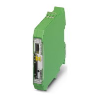
RAD-...-IFS
24 / 198
PHOENIX CONTACT 105542_en_05
3.6 Serial interfaces
The wireless modules have one RS-232 interface and one RS-485 2-wire interface. Con-
nect the I/O device to the wireless module via the corresponding interface.
3.6.1 Shielding of the RS-485 bus cable
• Connect the overall shielding braid of the RS-485 bus cable correctly via an external
shield connection clamp (e.g,. SKS 8-SNS35, Order No. 3062786).
Choose the type of the overall shielding braid according to the expected interference:
– Firstly, connect the shield on one side. This suppresses electrical fields.
– To suppress disturbances caused by alternating magnetic fields, connect the shield on
both sides. When doing so, ground loops must be taken into consideration. Galvanic
disturbances along the reference potential interfere with the useful signal, and the
shielding effect is reduced.
– If several devices are connected to a single bus, the shield must be connected to each
device (e.g., by means of clamps).
– Connect the bus shield to a central PE point using short, low-impedance connections
with a large surface area (e.g., by means of shield connection clamps).
– Activate and configure the RS-232 or RS-485 interface using the PSI-CONF software
(from page 38 onwards).
– You can only use one interface per wireless module. Parallel operation of both inter-
faces is not possible.
NOTE: Damage to the interface
If the shielding has been connected incorrectly, permanent, external disturbing pulses
may damage the interface.
Observe the polarity of the RS-485 2-wire cable and make sure that the shielding is con-
nected correctly.

 Loading...