Planning wireless systems
105542_en_05 PHOENIX CONTACT 143 / 198
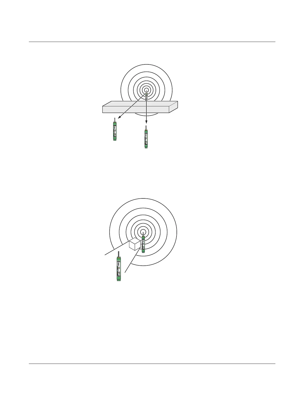
Also observe the angle between the transmitter and receiver. Depending on the angle, the
radio waves have to penetrate more or less material.
Figure 8-13 Angle of the transmitter and receiver
Radio dead spot
Radio dead spots are caused by impenetrable obstacles in the wireless path. A radio dead
spot can be compared to the shadow cast by the sun. If the receiver is located in a radio
dead spot, no direct radio waves can reach it. It can only receive reflections or diffracted
waves.
Figure 8-14 Radio dead spot
RAD-2400-IFS
RAD-ID
Reset
+24 V
0 V
RSSI-
RSSI+
ANT
SPORT
0 1
Pwr
Dat
Err
RXTX
D(A) D(B)
GND
RX
CO
1
NC
1
CO
2
TX
RAD-2400-IFS
RAD-ID
Reset
+24 V
0 V
RSSI-
RSSI+
ANT
SPORT
0 1
Pwr
Dat
Err
RXTX
D(A) D(B)
GND
RX
CO
1
NC
1
CO
2
TX
RAD-2400-IFS
RAD-ID
Reset
+24 V
0 V
RSSI-
RSSI+
ANT
SPORT
0 1
Pwr
Dat
Err
RXTX
D(A) D(B)
GND
RX
CO
1
NC
1
CO
2
TX
RAD-2400-IFS
RAD-ID
Reset
+24 V
0 V
RSSI-
RSSI+
ANT
SPORT
0 1
Pwr
Dat
Err
RXTX
D(A) D(B)
GND
RX
CO
1
NC
1
CO
2
TX
RAD-2400-IFS
RAD-ID
Reset
+24 V
0 V
RSSI-
RSSI+
ANT
SPORT
0 1
Pwr
Dat
Err
RXTX
D(A) D(B)
GND
RX
CO
1
NC
1
CO
2
TX

 Loading...

