Description of I/O extension modules
105542_en_05 PHOENIX CONTACT 123 / 198
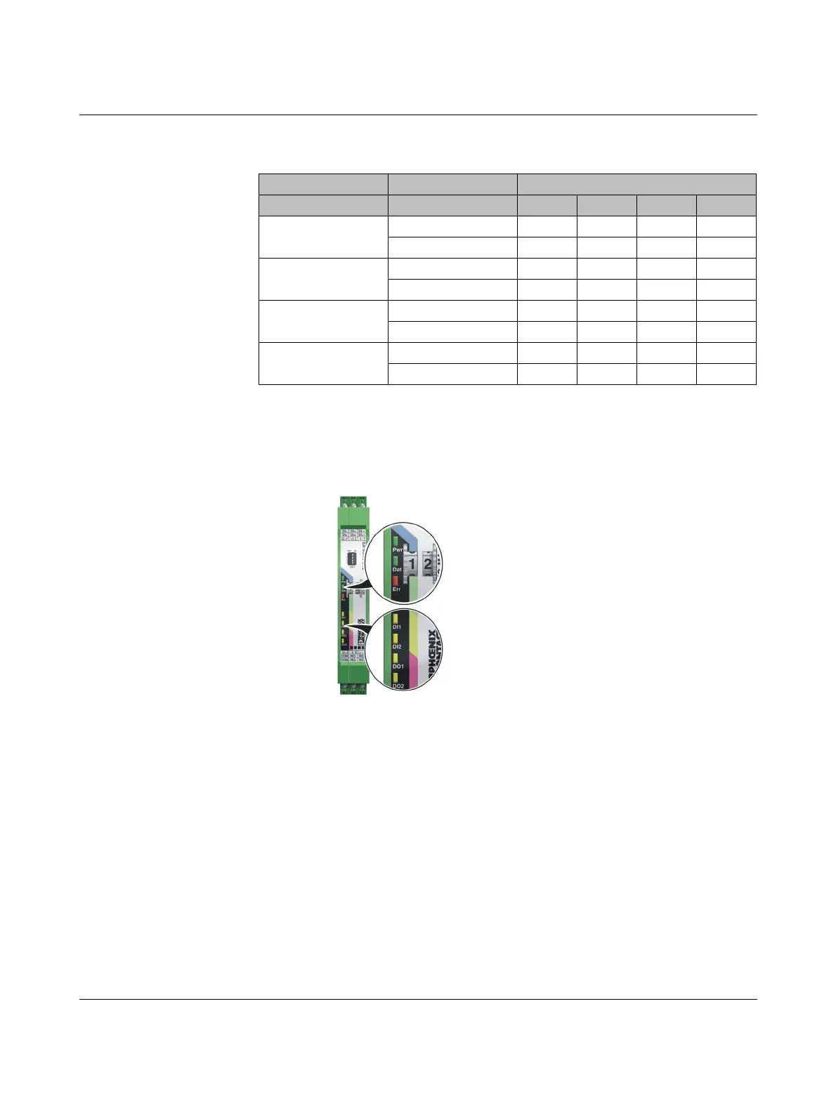
7.8.4 Diagnostic LEDs
The RAD-DAIO6-IFS I/O extension module uses a total of seven LEDs to indicate the oper-
ating states.
Figure 7-36 Diagnostics LEDs of the RAD-DAIO6-IFS
PWR LED
The green PWR LED indicates the status of the supply voltage.
DAT LED
The green DAT LED indicates the status of bus communication.
Table 7-14 DIP switches of the RAD-DAIO6-IFS
DIP switch
Setting Output signal 1 2 3 4
Analog IN
0 mA ... 20 mA OFF
4 mA ... 20 mA ON
Analog OUT
RESET OFF
HOLD ON
Digital OUT1
RESET OFF
HOLD ON
Digital OUT2
RESET OFF
HOLD ON
Off No supply voltage
On Supply voltage OK
Off No communication
Flashing Configuration and addressing mode
On Cyclic data communication

 Loading...

