RAD-...-IFS
44 / 198
PHOENIX CONTACT 105542_en_05
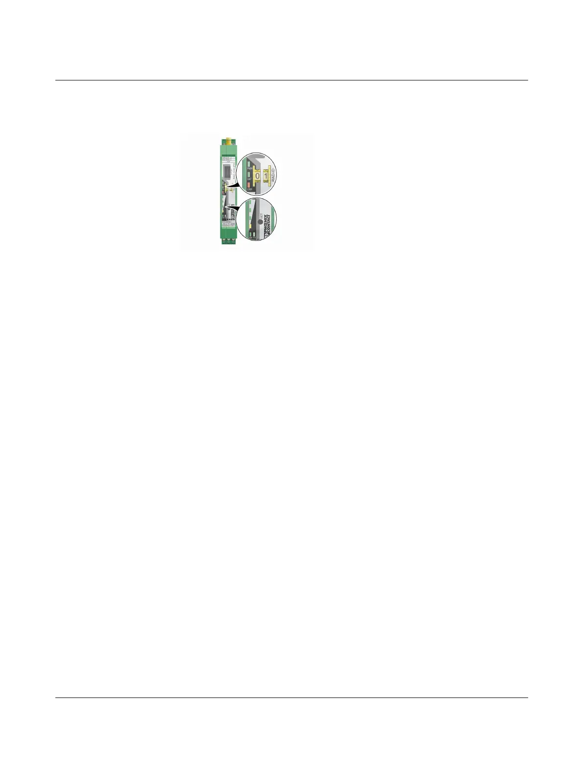
4.7 Diagnostics on the wireless module
A total of nine LEDs on the wireless module indicate the operating states.
Figure 4-13 Diagnostic LEDs on the wireless module
PWR LED
The green PWR LED indicates the status of the supply voltage.
DAT LED
The green DAT LED indicates the status of bus communication.
ERR LED
The red ERR LED indicates the error status.
Off No supply voltage
On Supply voltage OK
Off No communication
Flashing Configuration mode
On Cyclic data communication
Off No error
Flashing
Slow (1.4 Hz) Wireless module in I/O data mode
– Double assignment of I/O MAP address (e.g., two input
modules with the same I/O MAP address)
– Missing input module
– Missing output module
–RADID changed
Wireless module in PLC / Modbus/RTU mode
– Double assignment of I/O MAP address (e.g., two input
modules with the same I/O MAP address)
–RADID changed
– No Modbus communication
Fast (2.8 Hz) Wireless connection interrupted
On Local bus error, e.g., input or output module not read

 Loading...

