Description of I/O extension modules
105542_en_05 PHOENIX CONTACT 111 / 198
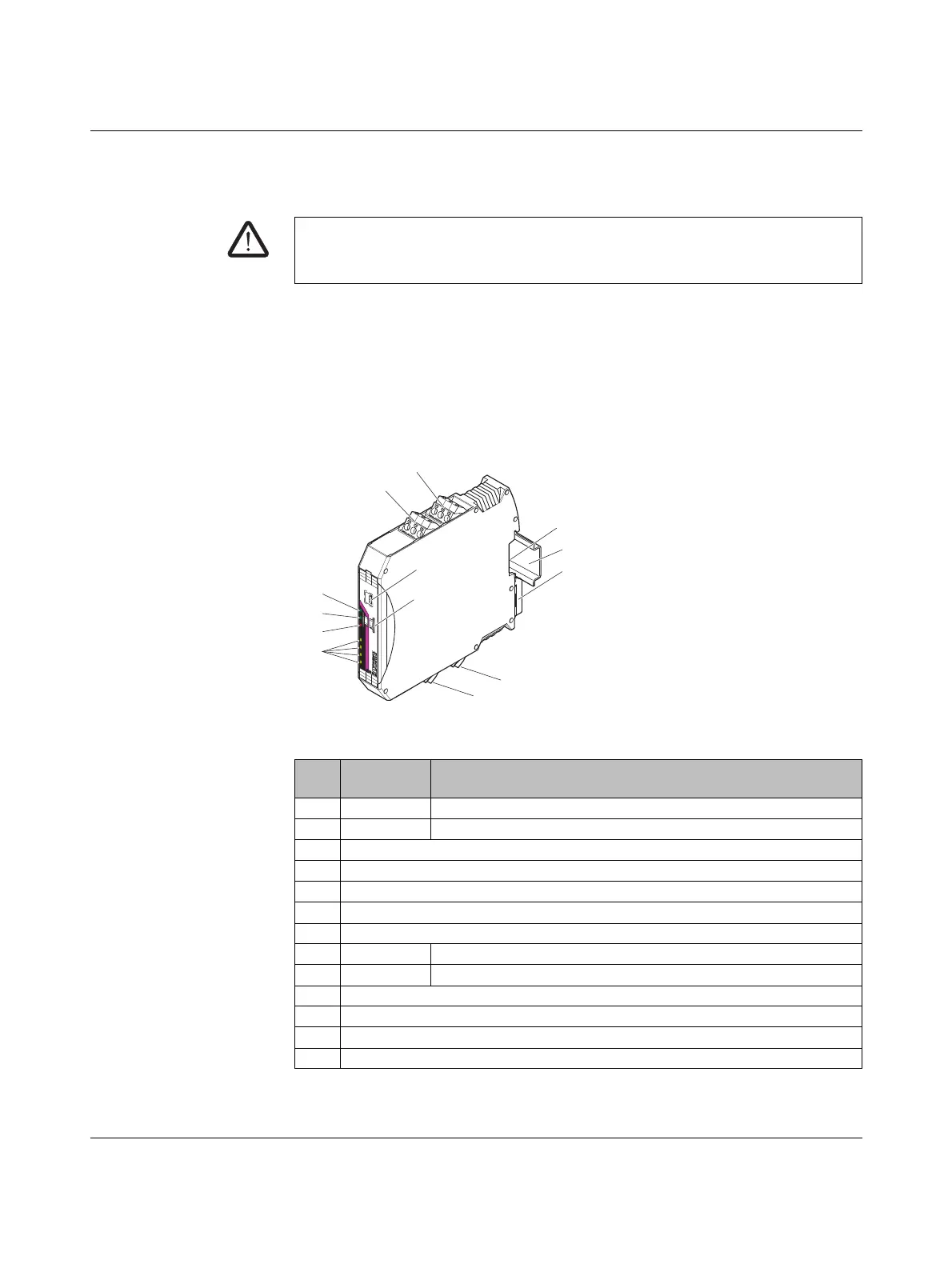
7.6 RAD-DOR4-IFS - digital extension module with four
outputs
The RAD-DOR4-IFS digital I/O extension module can process up to four input signals that
are switched via relay outputs. The digital outputs are designed as floating relay contacts
(changeover contacts). All outputs are electrically isolated from one another, from the sup-
ply voltage, and from the electronics.
7.6.1 Structure
Figure 7-25 RAD-DOR4-IFS structure
WARNING: Risk of electric shock
Use the same phase for digital inputs and outputs. The isolating voltage between the
individual channels must not exceed 300 V.
Item Ter mi na l
block
Designation
1 2.1/2.2/2.3 Relay output 2 with floating changeover contact
2 1.1/1.2/1.3 Relay output 1 with floating changeover contact
3 DIP switches for configuring the output behavior of the relay outputs (hold/reset)
4 White thumbwheel for setting the I/O MAP address
5 Connection option for DIN rail connector
6DIN rail
7 Metal foot catch for DIN rail fixing
8 5.1/5.2/5.3 Relay output 3 with floating changeover contact
9 6.1/6.2/6.3 Relay output 4 with floating changeover contact
10 Status LEDs for relay outputs DO1 ... DO4
11 ERR status LED, red (communication error)
12 DAT status LED, green (bus communication)
13 PWR status LED, green (supply voltage)
CO
M
4
CO
M
3
IO-MAP
RAD-DO
R4-IFS
NC
4
N
C
3
P
W
R
DA
T
E
RR
DO
1
D
O
2
D
O
3
DO
4
1
2
3
4
O
F
F
O
N
D
IP
-1
8
8
NO
4
N
O
3
C
OM
2
CO
M
1
N
C
2
NC
1
NO
2
N
O
1
COM
2
COM
1
NC
2
NC
1
NO
2
NO
1
1
2
4
5
7
8
13
12
11
9
6
10
3

 Loading...

