BRP-Rotax
Maintenance Manual
72-00-00
page 32
May 01/2007
Effectivity 912/914 Series
Edition 1 / Rev. 0
d02622
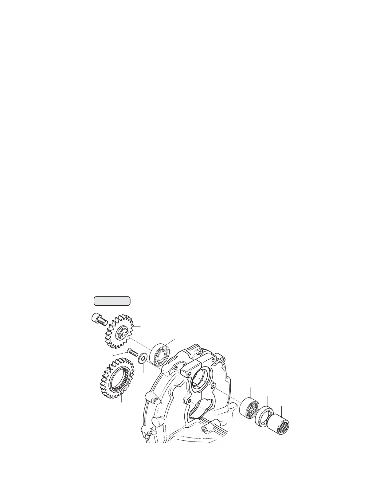
3.9.6) Vacuum pump drive removal
See Fig. 72-30.
The vacuum pump is driven via the drive gear (1) fitted on the propeller
shaft.
Check the ball bearing (2) and the needle sleeve (3). Check the gear-
tooth system of drive gear (1), the vacuum pump gear (4), the drive
sleeve (5) and the drive shaft of the vacuum pump.
If the ball bearing or needle sleeve are to be replaced, remove the
vacuum pump as follows:
Lock the drive sleeve (5) with the holder, part no. 242660, remove the
allen screw (6) M8x14 and remove the vacuum pump gear (4) with the
drive sleeve (5).
Remove the countersunk screw (7) M5x12 with the washer (8) for ball
bearing fixation.
Lift out the oil seal (9) and press out the needle sleeve and ball bearing
with a suitable step punch towards the propeller flange. Clean and
inspect bearing seat.
◆ NOTE: During this procedure, the needle sleeve (3), the oil
seal (9) and the ball bearing (2) are damaged and must
be replaced.
■ CAUTION : The attachment screw (6) M8 of the vacuum pump
gear for hydraulic governor drive is 16 mm long
(0.63 in.) and with a low screw head. For vacuum
pump drive, however, it is only 14 mm long
(0.55 in.) with standard screw head.
Fig. 72-30
00252
8
9
1
2
3
4
5
6
7
 Loading...


