Effectivity 912/914 Series
Edition 1 / Rev. 0
page 31
May 01/2007
d02623
73-00-00
BRP-Rotax
Maintenance Manual
3.3.11) Starting carburetor (choke)
See Figs. 73-25, 73-26 and 73-27.
Remove 4 countersunk screws M4x14 and remove the complete rotary
disc valve housing.
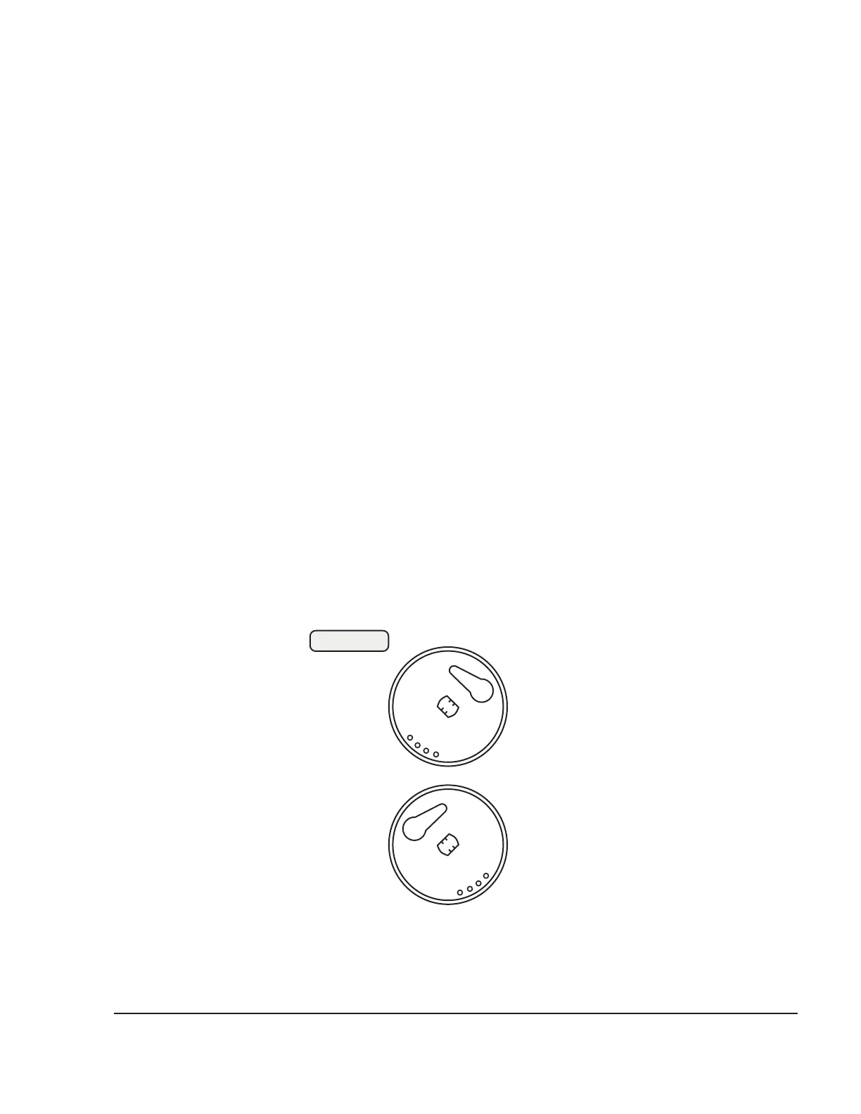
◆ NOTE: The shafts for the rotary disc valve have two markings,
L and R. The shaft marked R is for the carburetors for
cylinders 2/4, the shaft marked L for the carburetor for
cylinders 1/3. Fig. 73-25 shows the positions of the
markings on the choke shaft.
Remove hex. nut and pull the complete rotary disc valve from the
housing. Clean all parts and check.
◆ NOTE: The choke shaft (1) is marked with a dot (2). This mark
must point towards the cable engagement (3) or to
bore (4).
Clean all parts and blow out all bores and ducts with compressed air.
Check all parts and replace any defective ones.
◆ NOTE: SI-03-1998 ”Engine start at low temperatures”, latest
issue can be carried out to improve cold starting
performance.
L
R
Fig. 73-25
07404
carburetor 1/3
carburetor 2/4
3.3.12) Carburetor assembly
The carburetor with new O-rings and gaskets is assembled in reverse
order.