74-00-00
page 14
May 01/2007
Effectivity 912/914 Series
Edition 1 / Rev. 0
d02624
BRP-Rotax
Maintenance Manual
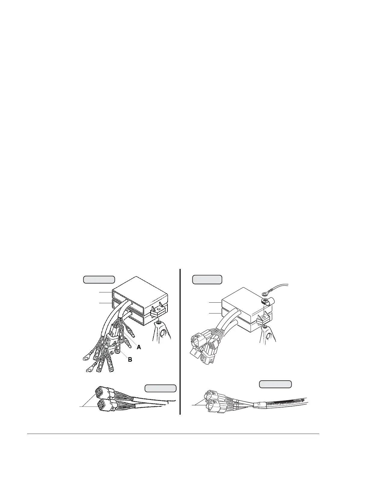
3.5) Electronic module, trigger coil kit
See Figs. 74-8, 74-9, 74-10 and 74-11.
■ CAUTION: On the 914 Series, the ignition points for circuit A and B differs
from that on ROTAX engine 912 ! In the event of failure of an
ignition circuit on the 914 Series, the two 6-pin plug connectors
(1) of the pick-up cables may be swapped over for localization
of the fault, only for the purpose of testing and at low throttle,
never at full throttle.
◆ NOTE: The ignition unit of the 912 Series and 914 Series have been
standardized. See SI-912-013 and SI-914-016,“Standardiza-
tion of the ignition unit“, latest issue.
The modules (2) are interchangeable as they are of the same design.
If the affected electronic module is replaced without success, there is a fault in
the charging coil or the trigger coils for this ignition circuit. Dismantling is
described here for both cases. See 74-00-00 sec. 3.19.
If the malfunction in the ignition circuit then appears again when the modules
have been interchanged, there is a fault in the electronic module.
Older engine models New engine models
Fig. 74-10
00398
A
00399
07725
Fig. 74-9
07724
Fig. 74-11
2
2
2
2
1
1
Fig. 74-8