75-00-00
page 14
May 01/2007
Effectivity 912/914 Series
Edition 1 / Rev. 0
d02625
BRP-Rotax
Maintenance Manual
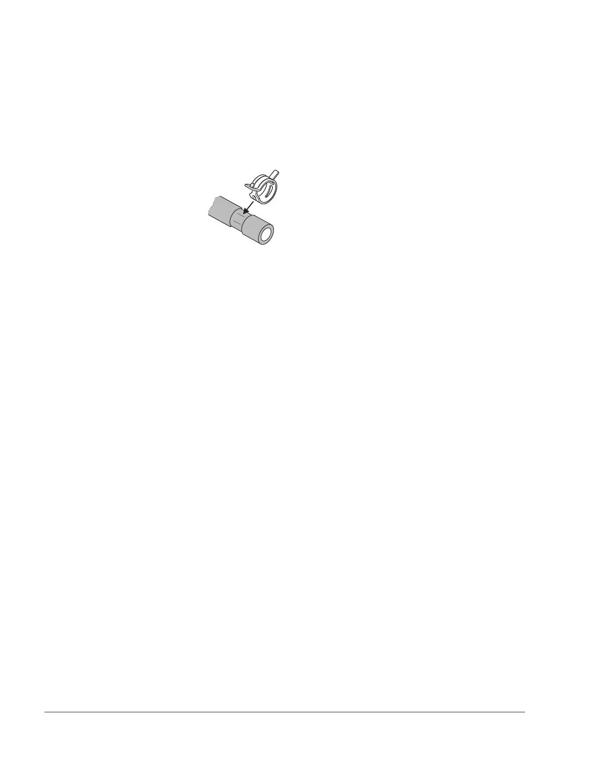
3.11) Coolant hoses fitting
See Fig. 75-12
■ CAUTION: The spring band hose clamps must be installed in the drawn
origin position. (See sketch)
Fit all coolant hoses (1) coming from the expansion tank to the coolant exit on
the cylinder heads (3) with spring band hose clamps (4). Also fit the coolant
hoses between the water pump (6) and the coolant entry (7) into the cylinder
heads with spring band hose clamps.
◆ NOTE: Position spring band hose clamps so that they cannot damage
neighboring coolant hoses.
On old engines designs the spring band hose clamps are not
installed.
3.12) Spring band hose clamps
Carry out visual inspection. Position the clamps so as to avoid contact and
friction with neighboring parts.
Use a suitable tool for assembly. See 00-00-00 sec. 10.6.
3.13) Radiator (optional 912/ 914 Series)
Clean radiator elements and check for damage, straighten fins if necessary. In
particular, check the hose connections and the support plates. Check for
tightness if leaks are suspected.
3.14) Cooling air duct (optional 912/ 914 Series)
The cylinders are ram-air cooled. The cooling air is pushed during flight and by
the propeller into the engine compartment and is distributed evenly by the
cooling air duct to the individual cylinders. Carry out visual inspection for
damage, cracks, chafing marks, burnt spots etc. In the event of noticeable
damage, replace the cooling air duct.
08341