BRP-Rotax
Maintenance Manual
Effectivity 912/914 Series
Edition 1 / Rev. 0
72-00-00
page 33
May 01/2007
d02622
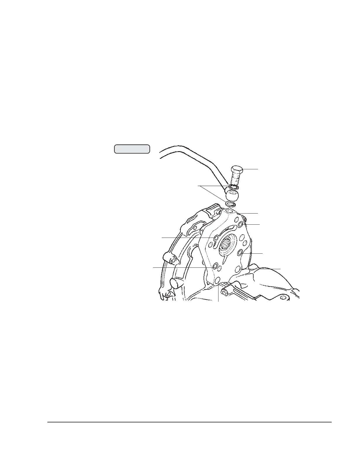
3.9.7) Propeller governor drive removal
See Figs. 72-31 and 72-32.
Remove banjo bolts (1) M10x1 and both sealing rings (2) from the
governor flange (3) and the oil pump housing and remove the oil line.
Remove the 4 allen screws (4) M6x20 and 2 allen screws (5) M6x16 for
oil inlet flange fixation. Remove governor flange with O-ring and
distance sleeve behind.
After removal of propeller gearbox the drive can be disassembled. Fix
the drive sleeve (9) with holder, part no. 242660. Unscrew allen screw
M8x16 (7) and remove the governor gear (8) with the drive sleeve (9).
Remove the countersunk screw (10) M5x12 with the washer for ball
bearing fixation.
Press out the needle sleeve (11) and the ball bearing (12) with a suitable
step punch towards the gearbox.
◆ NOTE: Needle sleeve and ball bearing will be damaged by this
procedure and must be replaced.
00256
1
2
3
4
5
4
4
4
5
Fig. 72-31