75-00-00
page 6
May 01/2007
Effectivity 912/914 Series
Edition 1 / Rev. 0
d02625
BRP-Rotax
Maintenance Manual
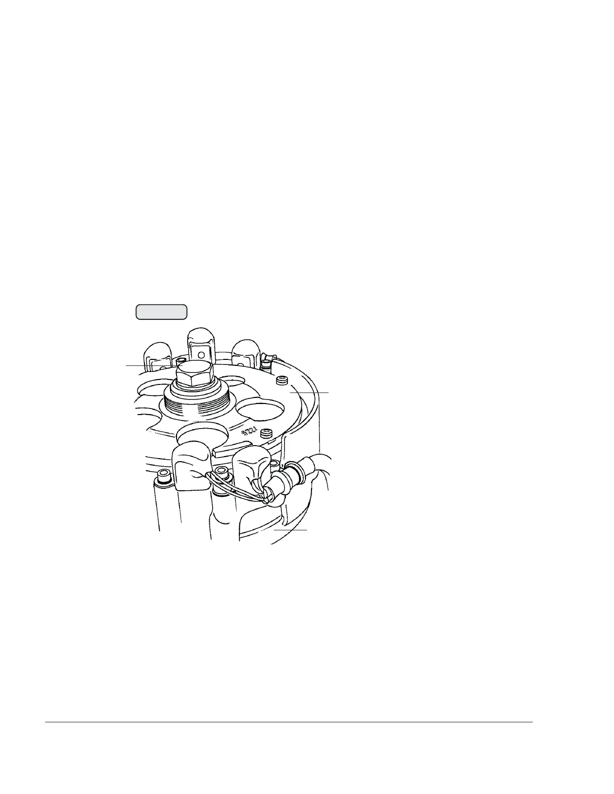
3.1) Water pump removal and inspection
See Fig. 75-2.
The water pump is integrated in the ignition housing. For repair work, fly wheel
hub (1) and the ignition housing (2) must be removed. On some engine
installations this requires removal or partial lifting of engine after loosening the
engine suspension.
To remove the hex. screw (3) M16x1.,5 from the fly wheel hub, the crankshaft
must be locked. See the corresponding Maintenance Manual (Line Mainte-
nance) for the respective engine type, 912 Series or 914 Series.
00344
2
1
3
Fig. 75-2