Effectivity 912 Series
Edition 1 / Rev. 0
page 55
May 01/2007
d02623
73-00-00
BRP-Rotax
Maintenance Manual
3.5.2) Fuel lines (on 912 Series)
See Figs. 73-47, 73-48, 73-49 and 73-50.
■ CAUTION: To prevent locked up stresses, all components should
first be screwed on loosely and then tightened to the
prescribed tightening torque.
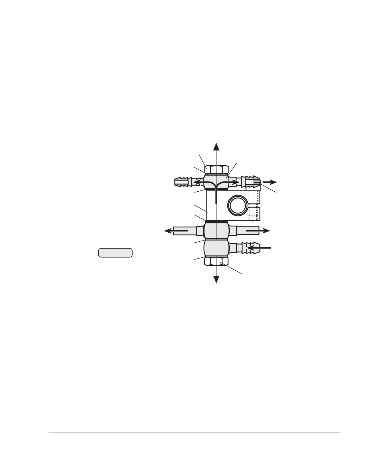
If the clamp block (1) has been removed, it must now be reattached with
an allen screw M5x16 and a tightening torque of 6 Nm (53 in.lb).
◆ NOTE: For easier assembly of the fuel line, observe the
original position of the clamp block.
The lines from the fuel pump (3) and the lines to the carburetors are
attached to the bottom side of the clamp block, each between a
sealing ring (2) and the banjo bolt (5) (tightening torque 10 Nm
(90 in.lb)).
The ring hose nipple (6) is attached to the top side of the clamp block
between a sealing ring (2) and the banjo bolt (5) (tightening torque 10
Nm (90 in.lb)).
– connection for return line to the tank (Ø outside 7mm (0.28 in.))
slip-on length: max. 17 mm (0.67 in.)
– connection to the pressure gauge (Ø outside 6 mm (0.24 in.))
slip-on length: max. 17 mm (0.67 in.)
zum Tank/
to fuel tank
zum Manometer/
to fuel pressure gauge
von der Pumpe/
from fuel pump
to carburetor
5
1
6
5
zum Vergaser/
to carburetor
zum Vergaser/
9
2
2
2
2
2
3
07512
Fig. 73-47
 Loading...


