Effectivity 914 Series
Edition 1 / Rev. 0
76-00-00
page 3
May 01/2007
d02626
BRP-Rotax
Maintenance Manual
2) Systems description
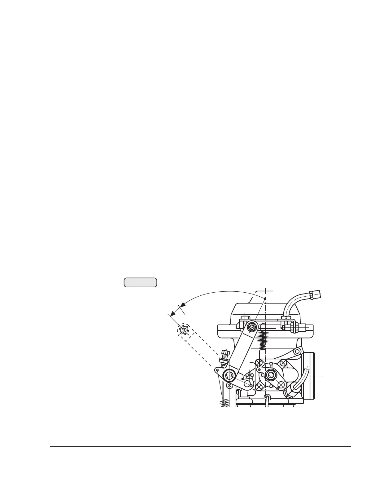
2.1) Turbocharger control (only on 914 Series)
2.1.1) Control of boost pressure in the airbox
See Figs. 76-1, 76-2, 76-3, 76, -4 and 76-5.
The position of the carburetor throttle valves is signalled by a potenti-
ometer to the TCU, where it is transformed in a chosen pattern into
target pressure in the airbox.
◆ NOTE: The positions of the throttle valve are divided into a
linear progression from 0 to 115 %.
After comparison of the actual airbox pressure with the target pressure,
the position of the wastegate will be varied by a servo motor until the
pressures are equal.
◆ NOTE: With carb throttle valve closed, a high boost pressure
is specified although hardly any exhaust gas energy is
available. The wastegate will then be completely closed
and the length of the Bowden cable between the servo
motor and the wastegate can be verified or adjusted.
100%
115%
0%
00137
Fig. 76-1