BRP-Rotax
Maintenance Manual
72-00-00
page 28
May 01/2007
Effectivity 912/914 Series
Edition 1 / Rev. 0
d02622
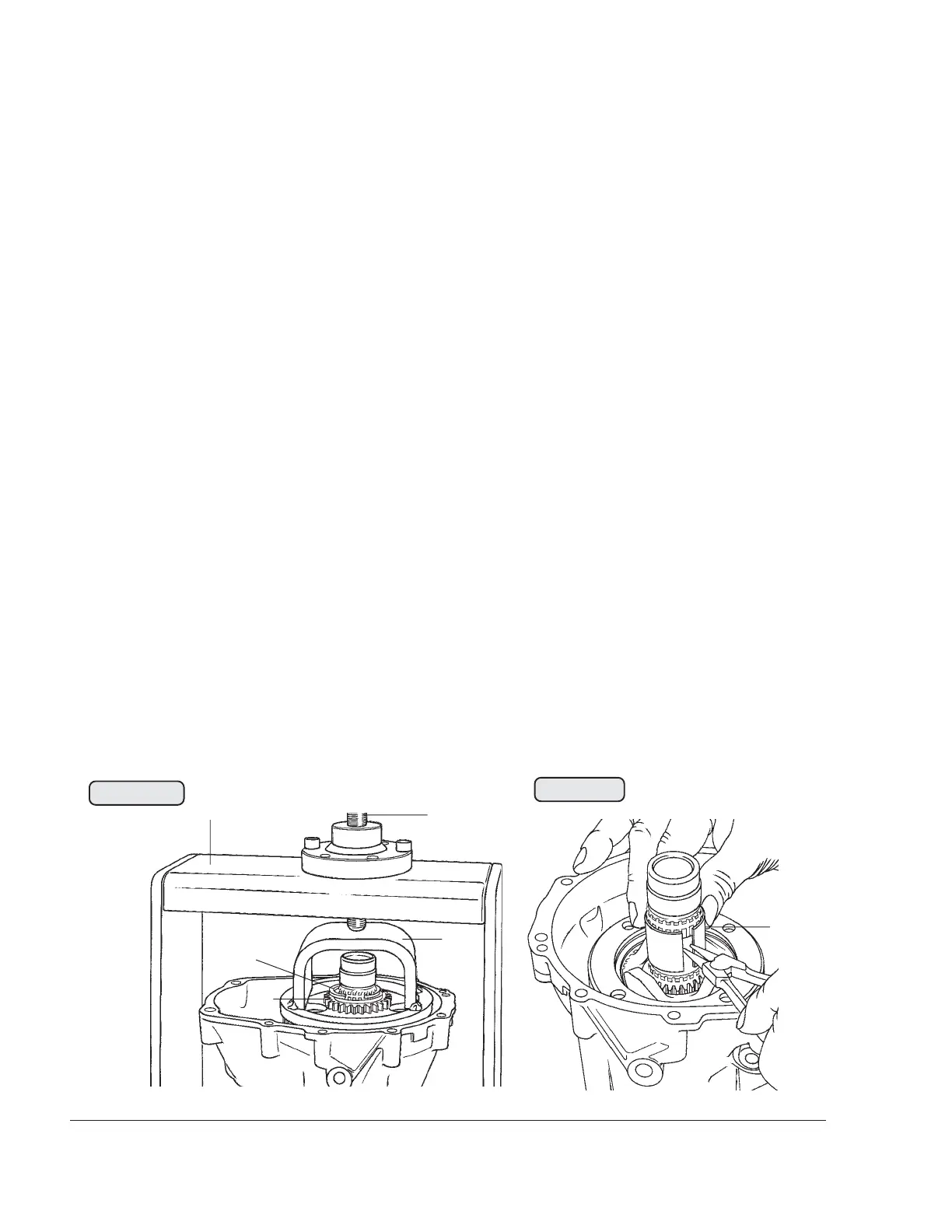
3.9.4) Propeller gearbox disassembly
See Figs. 72-25, 72-26 and 72-27.
■ CAUTION : Do not depress dog gear excessively, as this might
destroy the gearbox housing.
Place the complete gearbox in a suitable fixture (1) and press down the
gear wheel with the mounting yoke (2), part no. 876885, until the ring
halves (3) can be removed, see 00-00-00 sec. 10.4
■ CAUTION: Do not overstress bearing bushing (6), as otherwise it
will become unusable.
Now relieve the pressure on the gear by turning spindle (4) back and
remove the mounting yoke and the gearbox from the fixture. Remove
the drive gear (5), the thrust washer and the dog gear. Force bearing
bushing (6) apart with circlip pliers and withdraw from the propeller
shaft.
Remove the complete overload clutch (7) or dog hub (13), disc springs
(8) 80x35x3, step collar (9), 6 mm (0.236 in.) distance sleeve (17),
compensating shim (10), eccenter (11) (for fuel pump on the ROTAX
912 Series, of no significance on the 914 Series) and 8 mm (0.31in.)
distance sleeve (12).
■ CAUTION: The overload clutch is fitted in serial production on all
certified aircraft engines and on all noncertified aircraft
engines of configuration 3. All other engine versions
are equipped with a dog hub, but available with an
optional overload clutch or can be retrofitted to accom-
modate one.
00260
00261
Fig. 72-25
Fig. 72-26
1
2
3
4
5
6